


67
12
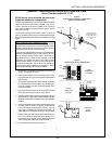
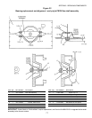
PS555G and PS570G rear wall thermocouples
with left-side terminal block connections
Thermocouples on these ovens are located on the rear wall.
They are secured in place by two screws that are inserted
through the holes in the thermocouple flange. The ovens
are equipped with a three-lead, flanged thermocouple iden-
tical to the one in this Kit.
NOTE FOR HIGH LIMIT THERMOCOUPLES:
These ovens have a high limit thermocouple installed in
the last mounting hole at the exit end of the oven.
The thermocouple supplied in this Kit can be used to
replace ANY of the temperature-sensing or high limit ther-
mocouples on the oven.
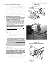
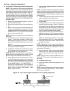
1. Remove the rear shrouds. Then, remove the cover over
the left blower motor. This allows access to the ther-
mocouples on the rear wall, and to the terminal block
inside the blower motor compartment.
Note that the thermocouples on these ovens are all
connected to the terminal block inside the left blower
motor compartment. It is not necessary to access the
right blower motor compartment.
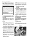
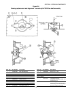
2. Remove the screws that hold the thermocouple to the
wall. Slide the thermocouple out of its mounting hole.
3. Disconnect the thermocouple leads from the terminal
block. Remove and discard the thermocouple.
4. Install the new thermocouple into its mounting hole.
Fasten it in place with the supplied #6 x 3/8 screws.
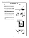
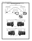
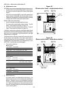
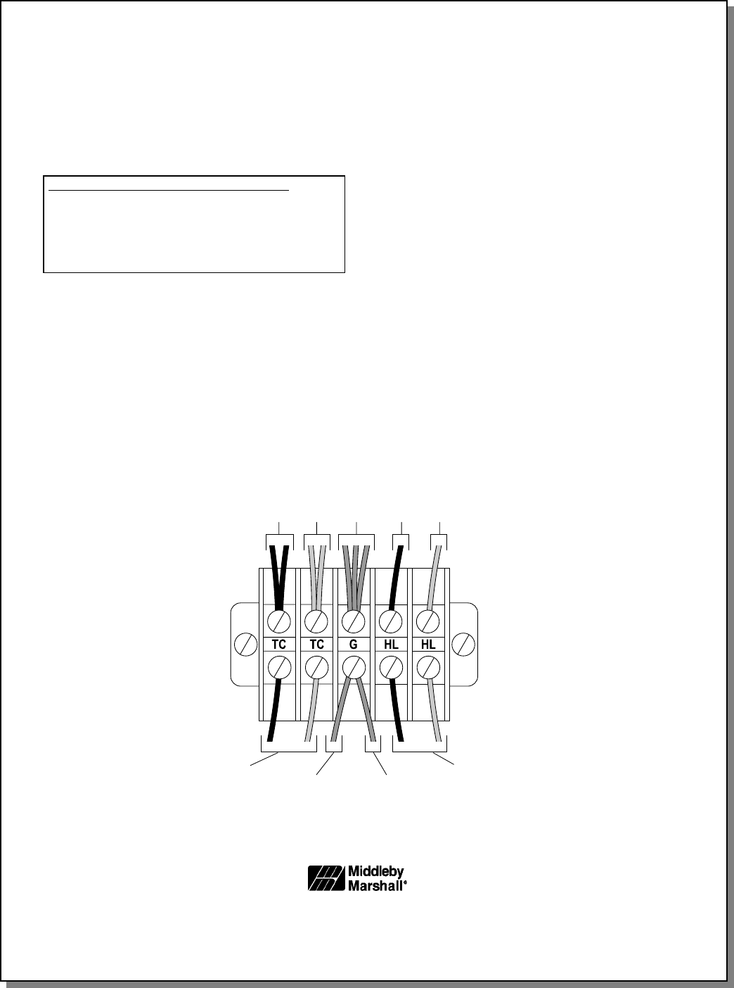
5. Wire the thermocouple as shown in Figure 16. Note
that the terminals are labeled - TC for temperature-
sensing thermocouple leads, G for ground leads, and
HL for high limit thermocouple leads.
6. Use the kit-supplied nylon clamp and #10-16 x 3/4
screw to secure the thermocouple leads so that they
will clear the shrouds, blower belts, and pulleys.
7. Replace all shrouds onto the oven.
Middleby Cooking Systems Group 1400 Toastmaster Drive Elgin, IL 60120 (847) 741-3300 FAX (847) 741-4406
Middleby Corporation Service Hotline 1-800-238-8444
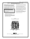
Figure 16
Thermocouple Wiring - PS555G and PS570G
To temperature
controller
To high limit
control module
White
(hi lim)
Red
(hi lim)
Ground
leads (all)
Red
(temp)
White
(temp)
To mounting screw
for high limit
control module
To ground
terminal on temp
controller
Appendix - Instructions for Service Kits 33984 and 33985 -
Oven Thermocouple Kit, 11/01
SECTION 3 - SERVICING COMPONENTS