


63
8
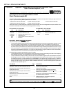
PS570 (X01-X05 name plate ID numbers) and
PS570S (early) with side-mounted thermo-
couples inside
or outside the blower motor
compartments
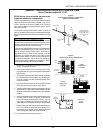
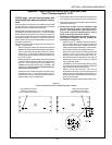
These ovens are equipped with two thermocouples, one on
each end wall of the oven. The thermocouples may be
mounted either inside or outside of the blower motor com-
partments.
The thermocouple on the right side of the oven has two
leads and sends its signal to the temperature controller.
The thermocouple on the left side of the oven is a dual-
function unit. It has FOUR LEADS and sends indi-
vidual signals to the temperature controller and the high
limit control module.
Installing this Kit will replace BOTH thermocouples with
current three-lead versions located on the back wall of the
oven. The Kit also requires the installation of a THIRD ther-
mocouple to act as a high limit sensor. Because of this,
you will need three separate thermocouple kits for these
ovens.
If the oven has already been updated with the rear-wall ther-
mocouple configuration, you can simply replace the affected
thermocouple. Follow the instructions for PS570S (late)
rear wall thermocouples on Page 10.
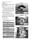
1. If the thermocouples are located outside the blower
motor compartments, remove and retain the thermo-
couple covers.
2. Remove the end plugs from the oven. Then, remove 1
or 2 air fingers from each end of the oven as necessary
to access the thermocouple mounting tubes.
3. Remove the rear shrouds. Open the blower motor com-
partment doors.
4. Remove the cooling fans from both blower motors. Then,
remove the blower belts.
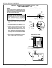
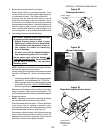
5. For each thermocouple:
Disconnect the thermocouple leads from the ter-
minal block inside the blower motor compartment.
Remove and discard the screws that hold the ther-
mocouple mounting tube to the plenum wall. Re-
move and discard the thermocouple and tube.
Plug the internal and external openings left by the
tubes using a high-temperature silicone sealant.
6. If the thermocouples were located outside the blower
motor compartments, replace the thermocouple cov-
ers.
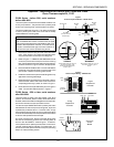
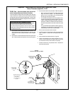
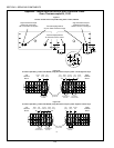
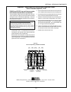
7. Refer to Figure 11. Measure and scribe marks in the
rear wall of the oven for drilling the thermocouple mount-
ing holes. Make sure that your measurements begin
at the edges of the rear panels, and NOT at the outer
edges of the oven!
Note that there are two different thermocouple placement
locations: one for Pizza Hut (and Pizza Hut International,
or Tricon) ovens, and one for all other ovens.
8. Drill the new thermocouple mounting holes using an
11/32 (8.73mm) D x 8 (203mm) L bit. Make sure that
you drill through all three walls of the oven.
9. Drill the two screw mounting holes for each thermo-
couple using a 7/64 (2.78mm) bit. Tap the holes using
a #6-32 tap.
10. If necessary, remove air fingers from the oven to ac-
cess the areas around the new thermocouple mount-
ing holes.
11. Vacuum out ALL drill shavings. If the oven is equipped
with a screen over the openings for the lower air fin-
gers, use a flexible hose extension on the vacuum to
reach the shavings through the upper air finger open-
ings.
12. Reinstall the air fingers and end plugs onto the oven.
13. Install the three new thermocouples into the back wall
of the oven. Check that the thermocouple flanges are
flush with the back wall.
14. Secure each thermocouple in place with the two kit-
supplied #6 x 3/8 screws.
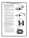
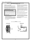
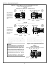
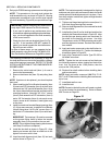
15. Wire the thermocouples as shown in Figure 12. The
thermocouples should be wired to the terminal block
inside the blower motor compartment closest to the
thermocouple.
IMPORTANT
As you wire the thermocouples, be sure to connect a
single chassis ground wire to the mounting screw for the
terminal block. See Figure 12.
A good ground connection for the thermocouples
uninsulated lead is REQUIRED for proper operation!
16. If you will be replacing additional thermocouples, re-
peat Steps 7-15 as necessary.
17. Using the kit-supplied nylon clamps and #10-16 x 3/4
screws, secure the thermocouple leads to the back
wall of the oven so that they will clear the shrouds,
blower belts, and pulleys.
18. Replace the blower belts and cooling fans.
19. Close the blower motor compartment doors. Replace
all shrouds onto the oven.
Appendix - Instructions for Service Kits 33984 and 33985 -
Oven Thermocouple Kit, 11/01
SECTION 3 - SERVICING COMPONENTS