


15
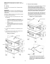
5. If it is necessary to add or remove conveyor links to
achieve the correct tension, OR if it is necessary to
reverse the conveyor belt for correct orientation, the belt
will need to be removed from the conveyor frame. If this
is necessary, perform the following procedure:
Remove the conveyor assembly from the oven and
place it flat on the floor.
Remove the master links using long-nose pliers.
Then, roll up the belt along the length of the
conveyor frame.
Add or remove belt links as necessary to achieve
the correct belt tension.
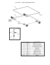
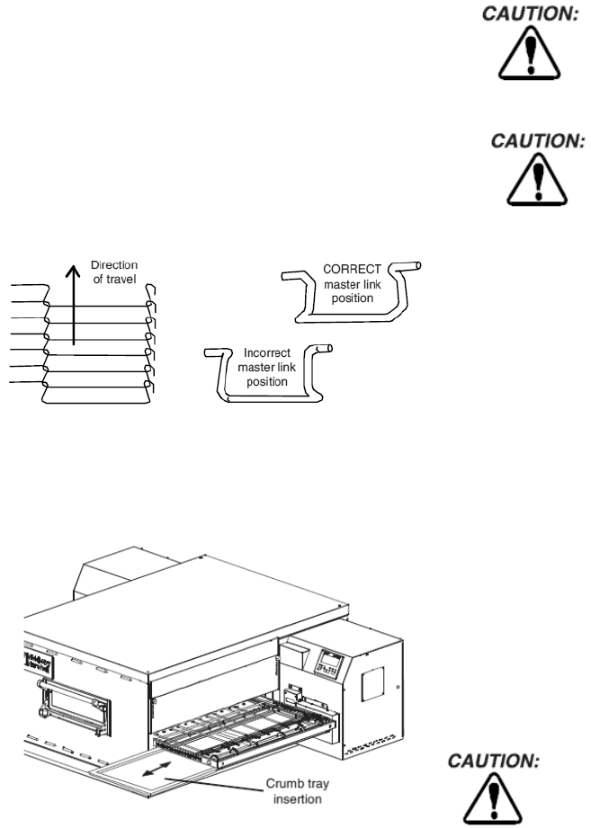
Replace the belt on the conveyor frame. Check that
the conveyor belt links are oriented as shown in
Figure 2-15, and that the smooth side of the
conveyor belt faces UP.
Connect the inside master links. Check that the
links are oriented as shown in Figure 2-15.
Connect the outside master links. Note that the
outside master links each have an open hook on
one side. This hook aligns with the hooks along the
sides of the other conveyor links. See Figure 2-15.
Replace the conveyor into the oven.
Figure 2-15. Conveyor and Master Link orientation
E. Final Assembly
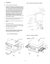
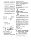
1. Install the crumb trays underneath the conveyor as
shown in Figure 2-16.
Figure 2-16. Crumb Trays
CONVEYOR BELT REVERSAL
Conveyor belt reversal consists of three steps:
1. Physically reversing the conveyor belt
2. Resetting the conveyor travel direction through the User
Interface.
3. Switching the photo sensor.
REVERSING THE CONVEYOR BELT
Remove the conveyor from the oven and find the master link
location. Remove master links and remove the belt from the
conveyor frame. Reassemble the belt back onto the frame
(in the reverse direction) and reinstall the master links.
Replace the conveyor assembly in the oven.
RESETTING DIRECTION
See OVEN CONFIGURATION MENU in the PS360G TECH
GUIDE. Direction is changed through the User Interface with
no wiring changes necessary.
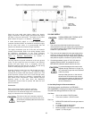
Shock hazard in compartments electrical
filters are electrically alive.
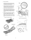
SWITCHING PHOTO SENSOR
Disconnect power before switching Photo
Eye.
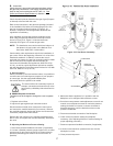
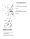
Remove the three screws securing the access door to the
unit. Open the access door and disconnect the connector
fitting to the photo eye assembly. Remove the two screws
securing the photo eye assembly to the control box. Remove
the four nuts securing the photo eye to the housing. Rotate
the photo eye 180 degrees and affix the photo eye with the
four nuts. On the opposite control box, remove the two
screws holding the cover where the photo eye assembly will
be positioned. Secure the photo eye assembly in position
with the two screws. Place the photo eye cover on the
opposite control box, where the photo eye assembly was
removed, and secure the two screws. Secure the access
door with the three screws. Remove the three screws
securing the access door on the opposite side. Open the
access door, where the photo eye is now positioned, and
connect the photo eye connector fitting. Secure the access
door with the three screws. Apply power to the unit. Adjust
the photo eye height by loosening the two screws securing
the photo eye assembly and sliding the photo eye assembly
either up or down, such that the beam is approximately 1/4
inch above the belt.
Note: This is MUCH easier in reduced light.
Replace all covers.
VI. ELECTRICAL SUPPLY
Authorized installation personnel normally
accomplish the connections for the ventilation
system, electric supply, and gas supply, as
arranged by the customer. Following these
connections, the factory-authorized installer
can perform the initial startup of the oven.
NOTE: The electric supply installation must satisfy the
requirements of the appropriate statutory authority such
as the National Electrical Code, CSA C22.2; the Australian
Code AG601; or other applicable regulations.
NOTE: The electric supply connection must meet all national
and local electrical code requirements.