


2
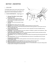
III. OVEN SPECIFICATIONS – PS360G
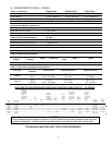
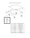
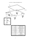
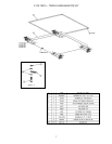
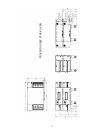
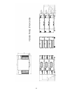
Table 1-1 Dimensions
Single Oven Double Oven Triple Oven
Overall Height 48.52” (1232.4 mm) 68.21” (1732.5 mm) 80.53” (2045.5 mm)
Overall Depth 57.40” (1458 mm) 57.40” (1458 mm) 57.40” (1458 mm)
Overall Length 92.00” (2337 mm) 92.00” (2337 mm) 92.00” (2337 mm)
Conveyor Width – Belt width is 32” 33.5” (850.9 mm) 33.5” (850.9 mm) 33.5” (850.9 mm)
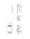
Recommended Minimum Clearances
Rear of Oven to Wall 0” (0 mm)
Right Side of Oven to Wall 2” (50.8 mm)
Left Side of Oven to Wall 2” (50.8 mm)
Table 1-2: General Specifications 32” Belt
Weight 1,100 lbs.
Rated Heat Input (per oven cavity) 119,900 BTU/hr
Maximum Operation Temperature 600°F
Air Blowers 4 at 2,800 rpm
Warm-up Time 20 minutes to 500°F
Table 1-3: Electrical Specifications
Main Blower
Voltage
Control Circuit
Voltage
Phase Frequency
Current
Draw
Poles Wires
230 VAC, 3φ 24VDC 1 50-60 Hz 7 Amps 2 3 Wire – L1, L2/N & GRND
Table 1-4: Gas Orifice and Pressure Specifications
Gas Type
Main Orifice
Diameter
Inlet Pressure Manifold Pressure Bypass Pressure
Natural
.120”
(#31)
6-8” W.C.
(14.9 - 19.9 mbar)
3.5” W.C. at manifold
(8.7 mbar)
0.35-0.36” W.C. at manifold
(0.9 mbar)
Propane
.0748”
(1.90mm)
11-14” W.C.
(27.4 – 34.9 mbar)
10.0” W.C.
(24.9 mbar)
0.9-1.0” W.C.
(2.2-2.5 mbar)
GAS ORIFICE AND PRESSURE SPECIFICATIONS (PER OVEN CAVITY) – CE OVENS
Gas
Type
Main Orifice
Diameter
AT,BG,CR,
CZ,DK,EE,
FI,GR,HR,
HU,IS,IE,
IT,LV,LT,
NO,PT,RO,S
K,SI,ES,
SE,CH,TR,G
B
NL
DE,
LU,
PL
BE,FR
FI,CR,GR,
IE,HR,LU,
NL,PL,SK,
SI,ES,CH,
TR,GB,CY,C
Z,DE,MT,SK
CY,CZ,
DE,
MT,SK
SW,CH,
AT,DK,
NO,FI,
NI,CR,
FR
BG,CY,CR,C
Z,DK,EE,FI,
GR,HR,
LV,LT,LU,
MT,NL,NO,S
K,SI,SE,
TR
PL /
AT,DE,
HU,SK,
CH
BE,CY,CZ,
EE,FR,
GR,IE,IT,
LT,LU,LV,P
T,RO,SK,E
S,CH,
GB,PL
Orifice
Manifold
Pressure
Rated
Heat
Input
I
2H
I
2L
I
2E
I
2E+
I
3P
I
3P
I
3B/P
I
3B/P
I
3B/P
I
3+
Natural
G20
.120
”
3.048 mm
20mbar --
20
mbar
20/25
mbar
-- -- -- -- -- --
3.5” w.c.
8.7mbar
35.2kW
Natural
G25
.120
”
3.048 mm
--
25
mbar
-- -- -- -- -- -- -- --
3.5” w.c.
8.7mbar
35.2kW
Butane
G30
.0748
”
1.90mm
-- -- -- -- -- --
28-30/50
mbar
30 mbar
37/50
mbar
28-30
mbar
10.0” w.c.
24.9 mbar
35.2kW
Propane
G31
.0748
”
1.90mm
-- -- -- -- 37 mbar 50 mbar -- 30 mbar
37/50
mbar
37 mbar
10.0” w.c.
24.9 mbar
35.2kW
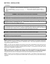
NOTE
Wiring Diagrams are contained in Section 5 of this Manual and are also located inside the oven
control compartment. Additional electrical information is provided on the oven’s serial plate.
THIS MANUAL MUST BE KEPT FOR FUTURE REFERENCE