


16
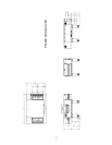
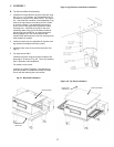
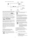
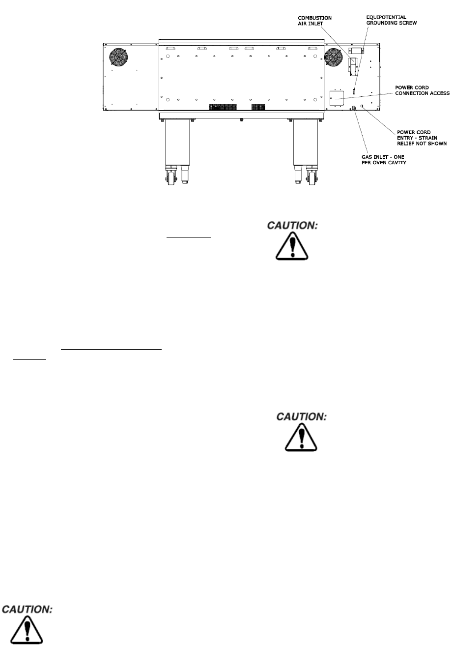
Figure 2-17. Utility Connection Locations
Check the oven serial plate before making any electric
supply connections. Electric supply connections must agree
with data on the oven serial plate. The location of the serial
plate is shown in Figure 1-1 (in Section 1, Description
).
A fused disconnect switch or a main circuit breaker
(customer furnished) MUST be installed in the electric supply
line for each oven cavity. It is recommended that the
switch/circuit breaker have Lockout/Tagout capability.
The supply conductors must be of the size and material
(copper) recommended. Refer to the wiring diagram inside
the machinery compartment of the oven. Electrical
specifications are also listed on the oven’s serial plate and in
Table 1-3, Electrical Specifications
(in Section 1,
Description
).
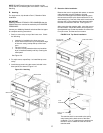
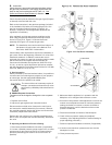
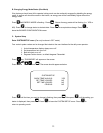
The oven requires a ground connection to the oven ground
screw. For gas ovens, the screw is located in the electrical
junction box (see Figure 2-14). If necessary, have the
electrician supply the ground wire. Do NOT use the wiring
conduit or other piping for ground connections.
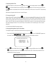
Incoming electrical power lines are fed through the strain-
relief fitting, shown in Figure 2-14. The electrical supply
connections are made inside the electrical junction box. The
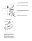
power lines then connect to the oven circuits through safety
switches located inside the machinery compartment and
each blower motor compartment. These switches interrupt
electrical power to the oven when the Machinery
Compartment Access Panel is opened, OR when the rear
panel is removed.
Connection
Refer to the wiring diagram inside the machinery
compartment of the oven to determine the correct
connections for the electrical supply lines. Connect the
supply as indicated on the wiring diagram.
The terms of the oven’s warranty require all
start-ups, conversions and service work to be
performed by a Middleby Marshall Authorized
Service Agent.
VII. GAS SUPPLY
DURING PRESSURE TESTING NOTE
ONE OF THE FOLLOWING:
1. The oven and its individual shutoff valve must be
disconnected from the gas supply piping system during
any pressure testing of that system at test pressure in
excess of ½ psi (3.45 kPa).
2. The oven must be isolated from the gas supply piping
system by closing its individual manual shutoff during
any pressure testing of the gas supply piping system at
test pressure equal to or less than ½ psi (3.45 kPa).
3. If incoming pressure is over 14” W.C. (35 mbar), a
separate regulator MUST be installed in the line
BEFORE the individual shutoff valve for the oven.
To prevent damage to the control valve
regulator during initial turn-on of gas, it is
very important to open the manual shutoff
valve very slowly.
After the initial gas turn-on, the manual
shutoff valve must remain open except
during pressure testing as outlined in the
above steps or when necessary during
service maintenance.
A. Gas Utility Rough-In Recommendations
The following system specifications are STRONGLY
RECOMMENDED. Deviating from these recommendations
may affect the baking performance of the oven.
Gas Meter
One or two cavities: 750 CFH meter
Three oven cavities: 1,200 CFH meter
Gas Line
DEDICATED GAS LINE from the gas meter to
the oven
2” (50.8mm) pipe for Natural gas
2” (50.8mm) pipe for Propane
Maximum length: 2.002 (61m). Each 90° elbow
equals 7’ (2.13m) of pipe.