


11
ENGLISH
VIII. GAS SUPPLY
CAUTION
DURING PRESSURE TESTING NOTE ONE OF THE FOLLOW-
ING:
1. The oven and its individual shutoff valve must be
disconnected from the gas supply piping system during
any pressure testing of that system at test pressure in
excess of 3.45 kPa.
2. The oven must be isolated from the gas supply piping
system by closing its individual manual shutoff valve
during any pressure testing of the gas supply piping
system at test pressure equal to or less than 3.45 kPa.
3. If incoming pressure is over 50mbar, a separate regu-
lator MUST be installed in the line BEFORE the individual
shutoff valve for the oven.
WARNING: To prevent damage to the control valve regu-
lator during initial turn- on of gas, it is
very important to
open the manual shutoff valve
very slowly.
After the initial gas turn-on, the manual shutoff valve must
remain open except during pressure testing as outlined
in the above steps or when necessary during service
maintenance.
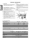
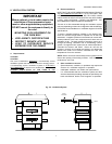
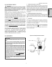
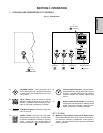
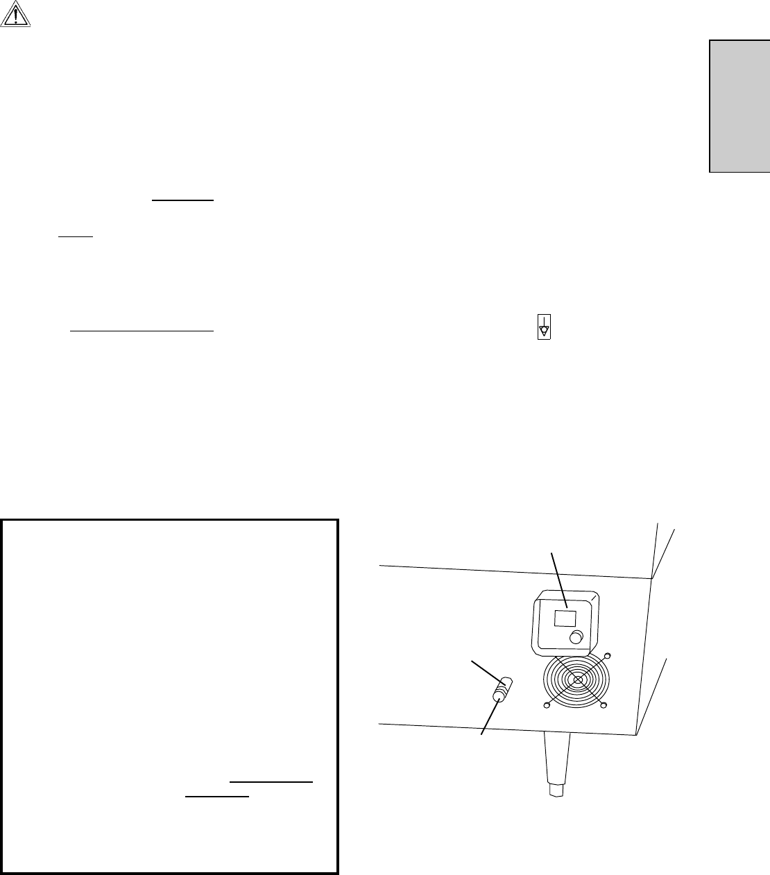
Figure 2-14 - Utility Connection Locations
Electrical
Junction Box
Gas ovens:
19mm pipe for
gas utility connection
Electric ovens:
Cutout for electrical
connection
VII. ELECTRICAL SUPPLY
WARNING
Authorized supplier personnel normally accomplish
the connections for the ventilation system, electric supply,
and gas supply, as arranged by the customer. Following
these connections, the factory-authorized installer can
perform the initial startup of the oven.
NOTE: All aspects of the electrical supply connection must
comply with current IEC/CEE requirements and with all
applicable local, national, and international codes.
Check the oven serial plate before making any electric supply
connections. Electric supply connections must agree with data
on the oven serial plate. The location of the serial plate is shown
in Figure 1-1 (in Section 1,
Description).
A fused disconnect switch or a main circuit breaker (customer
furnished)
MUST be installed in the electric supply line for each
oven cavity. The circuit breaker/disconnect must have 3mm
contact gaps breaking all poles of the supply. It is recommended
that this circuit breaker/disconnect have lockout/tagout capability.
The supply conductors are to be 90°C-rated copper wiring.
Additional wiring information is shown on the wiring diagrams
in Section 5,
Electrical Wiring Diagrams and inside the machin-
ery compartment of the oven.
The oven requires a ground connection to the oven ground
screw located in the electrical junction box. (The box is shown
in Figure 2-14.) The ground connection must comply with
current IEC/CEE requirements and with all applicable local,
national, and international codes. If necessary, have the
electrician supply the ground wire. Do NOT use the wiring
conduit or other piping for ground connections!
A. Additional Information - Gas Ovens
All electric supply connections are made via the electrical
junction box on the rear of the oven, shown in Figure 2-14. The
power lines then connect to the oven circuits through safety
switches located inside the machinery compartment and each
blower motor compartment. These switches interrupt electric
power to the oven when the Machinery Compartment Access
Panel is opened, OR when either of the blower or rear shrouds
is removed.
B. Additional Information - Electric Ovens
A cutout in the back wall of the machinery compartment provides
access to the electrical supply connections. See Figure 2-14.
The actual wiring connections are made at the electrical junction
box.
C. Connection
Refer to the wiring diagram inside the machinery compartment,
or in Section 5 of this Manual, to determine the correct
connections for the electrical supply lines. Connect the supply
as indicated on the wiring diagram.
If required by national or local codes, connect an equipotential
ground wire to the lug next to the
symbol. The equipotential
ground connection must meet all applicable national and lo-
cal code requirements.
SECTION 2 - INSTALLATION