13
ENGLISH
C. Preparation for Use with Various Gases
Before proceeding to set up the oven for a specific gas, check
that the main gas supply valve and the circuit breaker/fused
disconnect are in the OFF ("O") position.
The main and pilot orifices must match the sizes shown in the
Gas Orifices and Pressure Specifications table, near the
beginning of this Section. If necessary, replace the orifices.
Refer to Part D,
Replacing the Gas Orifices.
The orifice (manifold) pressure should be adjusted to the value
shown in the Gas Orifices and Pressure Specifications table for
the specific gas type and location.
1. For Use with Natural Gas
The actual heat input to the oven must match the rated heat
input. The input to the burner can be determined using the
orifice (manifold) pressure data or by the volume supplied
using the gas meter. Both of these procedures are
described in Part F,
Adjusting the Orifice (Manifold) Pressure
and Heat Input.
If the measured input does not correspond with the rated
input (shown in the Gas Orifices and Pressure Specifications
table), check first that the correct orifices are installed. If the
orifices are correct, check and correct the supply and orifice
pressures to obtain the correct input based on the gas
meter reading.
2. For Use with Liquid Propane (LP) Gas
When using liquid gas, the converter in the multifunction
gas valve must be removed, and then replaced INVERTED
from its former position. See Figure 2-16. Inverting the
converter will disable the governor. This step is only
required if the supply pressure is below 50mbar.
D. Replacing the Gas Orifices (if so required)
1. Replacing the Main Orifice
a. Check that the main gas supply valve and the circuit
breaker/fused disconnect are in the OFF ("O") position.
b. Open the union in the gas supply line. The union is
shown in Figure 2-16, on the previous page.
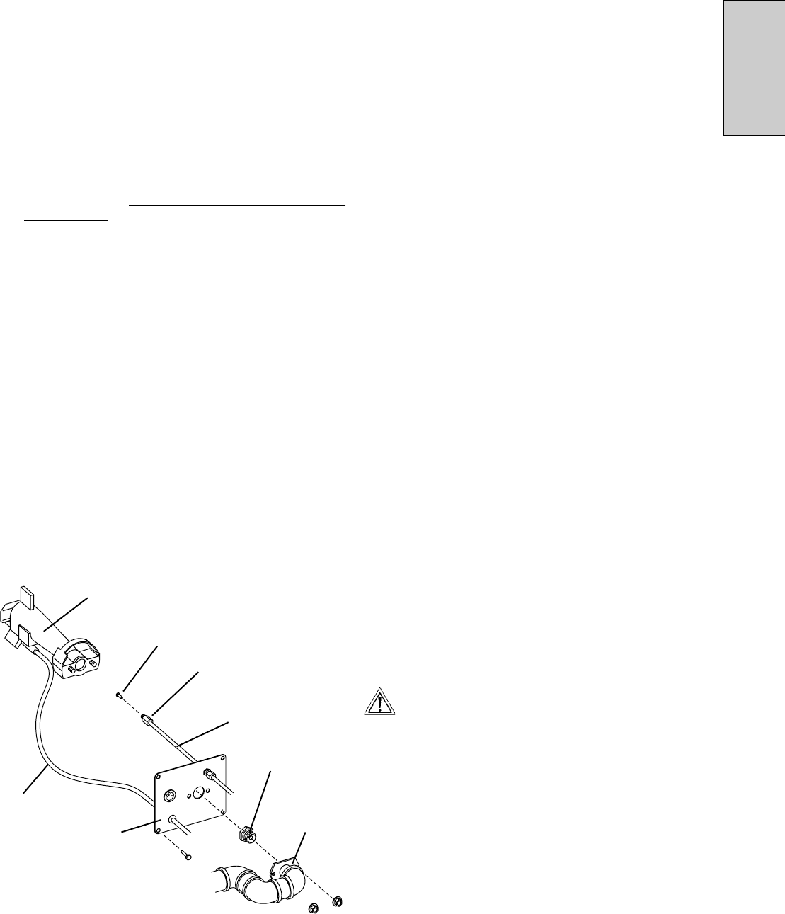
c. Refer to Figure 2-17. Unscrew the four hex screws that
hold the venturi mounting plate to the front of the
burner. Remove the gas train/venturi assembly from
the oven.
d. Remove the two 1/2" nuts that secure the gas train to
the venturi mounting plate.
e. Remove the main orifice using an 11/16" wrench.
f. Install the new orifice.
2. Replacing the Pilot Orifice
NOTE: All natural gases use the same size pilot orifice
(0,635mm), as do all liquid propane (LP) gases (0,381mm).
Because of this, it is not normally necessary to replace the
pilot orifice unless converting the oven from natural to
propane, or from propane to natural, operation.
a. Refer to Figure 2-17. Unscrew the pilot tube
compression nut and slide it out of the way. Pull the
tube from the fitting to expose the pilot orifice.
b. Remove the pilot orifice.
c. Slip the new pilot orifice into the pilot tube.
d. Push the pilot tube back into place until it bottoms, and
hold it in place. Slide the compression nut back into
place and engage the threads. Tighten the nut to a
snug fit with your fingers.
e. Gently tighten the nut one complete turn with a wrench.
DO NOT OVERTIGHTEN THE COMPRESSION NUT.
3. Replacing the Bypass (Low Flame) Orifice
a. Refer to Figure 2-16. Note the locations of the 1/2" hex
compression nuts that hold the bypass line in place.
Loosen the compression nuts using a 1/2" wrench.
b. Remove the bypass tube. Then, remove the bypass
orifice from the tube.
c. Slip the new orifice into the bypass tube.
d. Replace the tube onto its fittings on the solenoid valve.
While holding the tube in place, slide the compression
nuts back into place and engage the threads. Tighten
the nut to a snug fit with your fingers.
e. Gently tighten the nuts one complete turn with a wrench.
DO NOT OVERTIGHTEN THE COMPRESSION NUTS.
f. Replace the gas train and venturi by following Steps a-
d in
Replacing the Main Orifice, above, in reverse order.
WARNING
After completing these procedures, perform a gas
leak test before operating the oven.
Figure 2-17 - Replacing the Main and Pilot Orifices
Main
orifice
Pilot
orifice
Pilot tube
Compression
nut
Main orifice
holder (attached
to gas train)
Venturi
assembly
Venturi
mounting
plate
Ignition
sensor
wire
SECTION 2 - INSTALLATION


