


14
ENGLISH
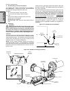
E. Checking the Gas Supply (Inlet) Pressure
1. Remove the supply (inlet) pressure cap screw from the
multifunction gas valve. Attach a manometer to the stud.
2. Depress the machinery compartment safety switch to
allow the oven to operate.
3. Open the main gas supply valve. Switch the circuit breaker/
fused disconnect to the ON ("I") position.
4. Start the oven and adjust the temperature controller to the
maximum setting (288°C).
5. Measure the supply (inlet) pressure.
6. Switch the oven off. Close the main gas supply valve, and
switch the circuit breaker/fused disconnect to the OFF ("O")
position. Remove the manometer, and replace the cap
screw onto the multifunction gas valve.
7. Compare the measured supply (inlet) pressure to the
nominal pressures shown in the Gas Orifices and Pressure
Specifications table.
If the supply pressure is lower or higher than the nominal
pressure, the reason should be investigated and the gas
supplier contacted.
For natural gas ovens, if the measured supply pressure is lower
than 17mbar, or higher than 25mbar, contact the gas supplier.
DO NOT OPERATE THE OVEN or adjust the oven controls.
F. Adjusting the Orifice (Manifold) Pressure and Heat Input
To use the orifice pressure method, you must know the specific
gas type and quality used. If using the orifice pressure method,
you should double-check the input using the volumetric method.
To use the volumetric method, you must know the heat value
(HuB) of the gas used. This information is available from your
gas supplier.
During these measurements, do not operate any other
appliances that use the same gas meter as the oven.
1. Orifice (Manifold) Pressure Method
a. Check that the main gas supply valve and the circuit
breaker/fused disconnect are in the OFF ("O") position.
b. Remove the regulated (manifold) pressure cap screw
from the multifunction gas valve. Attach a manometer
to the stud.
c. Remove the cap screw from the pressure adjustment
screw (governor) on the multifunction gas valve.
d. Depress the machinery compartment safety switch to
allow the oven to operate.
e. Open the main gas supply valve. Switch the circuit
breaker/fused disconnect to the ON ("I") position.
f. Start the oven and adjust the temperature controller to
the maximum setting (288°C).
g. Adjust the pressure adjustment screw as necessary
to match the correct pressure for the oven's specific
gas type. Refer to the Gas Orifices and Pressure
Specifications table. Turning the adjustment screw
clockwise increases the flow, while turning it
counterclockwise reduces the flow.
h. Switch the oven off. Close the main gas supply valve,
and switch the circuit breaker/fused disconnect to the
OFF ("O") position. Remove the manometer, and
replace the cap screws onto the multifunction gas
valve.
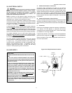
Consumption (m
3
/hr.) =
NB (Rated input in kW)
HuB (Heat [Calorific] value
of gas in kW/m3)
=
Time (in minutes) of
0.1m3 of gas usage
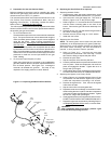
2. Volumetric Method
a. Determine the time of 0.1m
3
(100 liters) of gas usage
as follows.
b. Check that the main gas supply valve and the circuit
breaker/fused disconnect are in the OFF ("O") position.
c. Remove the cap screw from the pressure adjustment
screw (governor) on the multifunction gas valve.
d. Depress the machinery compartment safety switch to
allow the oven to operate.
e. Open the main gas supply valve. Switch the circuit
breaker/fused disconnect to the ON ("I") position.
f. Start the oven and adjust the temperature controller to
the maximum setting (288°C).
g. Adjust the pressure adjustment screw as necessary
to match the calculated volume using the time (in
minutes) of 0.1m
3
of gas usage. Turning the
adjustment screw clockwise increases the flow, while
turning it counterclockwise reduces the flow.
h. Record the reading obtained from the gas meter and
calculate the obtained gas flow. Compare this value
to the information in the Gas Orifices and Pressure
Specifications table.
i. Switch the oven off. Close the main gas supply valve,
and switch the circuit breaker/fused disconnect to the
OFF ("O") position. Replace the cap screw onto the
multifunction gas valve.
6
Consumption
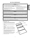
SECTION 2 - INSTALLATION