


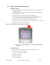
Bulletin Number Chapter 2: Functional Description 14 of 102
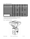
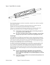
Figure 2: Equipment Specifications
150 500 900 2500 4000 6000
150 (68) 500 (227) 900 (410) 2500 (1135) 4000 (1815) 6000 (2725)
2 to 4 2 to 6
2.0 (50) 2.5 (63)
1.5 (38) 2.0 (50)
0.7 (20) 5.2 (145)
0.2 (5) 3.6 (100)
0.07 (2) 0.18 (5) 0.38 (11) 0.82 (23) 1.23 (34) 2.17 (61)
1.5 (0.7) 4 (1.8) 8 (3.6) 25 (11.3) 35 (15.8) 45 (20.4)
1 @ 5 kg 2 @ 3 kg 2 @ 5kg 2 @ 10 kg 2 @ 15 kg 2 @ 20 kg
0.18 (5) 0.25 (7) 0.56 (16) 1.1 (31)
1/8 (0.09)
42
2.5 (63)
250 (115) 375 (170) 450 (205) 650 (295)
350 (160) 475 (215) 550 (250) 800 (360)
Height (5) 34.5 (875) 51.5 (1308) 56.5 (1435) 69.5 (1765) 85.5 (2172) 89.5 (2273)
Width (5) 26.0 (650) 37.5 (952) 37.0 (940) 45.5 (1156)
Depth (5) 22.0 (560) 37.0 (940) 40.0 (1016) 46.5 (1181)
(2) Compressed air loaders cannot be used to load 150 # blenders.
(3) See page 2 for important rate information concerning each model's maximum blending rate.
(4) Hopper capacity measured as level full volume. Capacity reduced when loaded automatically.
(5) Measurements describe standard unit without feeder or R.A.M. hoppers.
Approximate Dimensions, in. (mm)
57.5 (1461)
57.0 (1448)
(1) Blender models with 7th and 8th component metering include Allen Bradley 10 inch color touch screen standard.
Weight of Machine (approx.), lbs. (kgs) 1100 (500)
Shipping Weight (approx.), lbs. (kgs) 1300 (590)
Mixer RPM 21 22
Blended Material Discharge Opening, in. (mm) 3.0 (76.2) 4.0 (102)
2.72 (77)
Mixer Motor Size, HP (kw) 1/6 (0.124) 1/3 (0.248)
Weigh Hopper Capacity, cu.ft. (l.)
Typical Batch Size, lbs. (kgs)
Load Cell Capacity, kgs
Mixer Capacity, cu.ft. (l.)
Supply Hopper Capacity - Majors, cu.ft. (l.) (4)
2.5 (70) 14.3 (400)
Supply Hopper Capacity - Minors, cu.ft. (l.) (4)
1.8 (50) 10.2 (285)
Slide Gate Size - Majors, in. (mm)
2.0 (50) 4.0 (102)
Slide Gate Size - Minors, in. (mm)
1.5 (38) 3.0 (76)
Dimensions and Specifications
Maximum Blending Rate, lbs/hr (kgs/hr) (3)
Number of Materials to be Blended 2 to 8
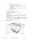
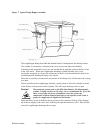
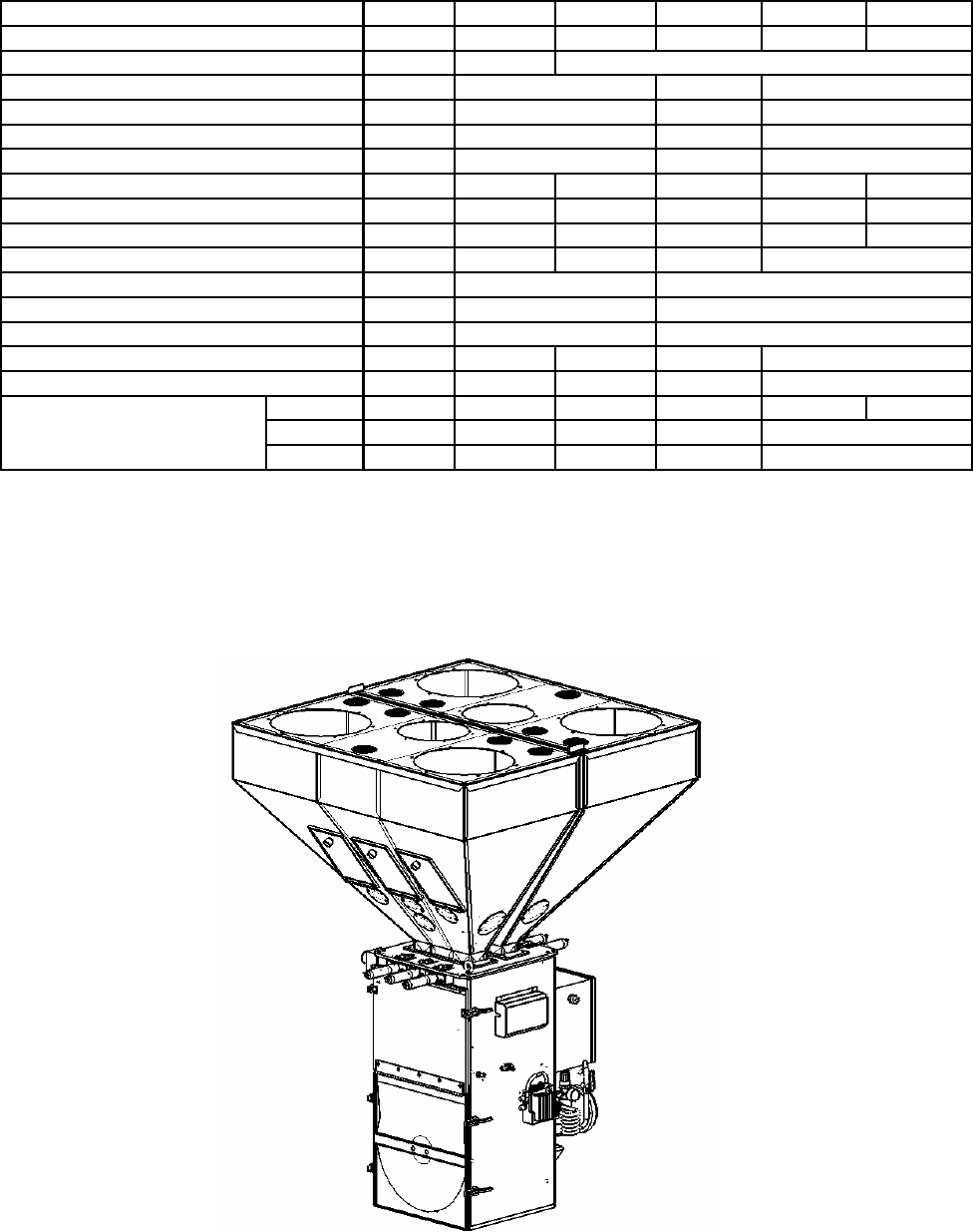
Figure 3: Typical Blender Assembly