


R-480J
11
TEST PROCEDURES
PROCEDURE
LETTER
COMPONENT TEST
B. Continuity check must be carried out with measuring instrument which is set to the highest resistance
range.
C. A normal capacitor shows continuity for a short time (kick) and then a resistance of about 10MΩ after
it has been charged.
D. A short-circuited capacitor shows continuity all the time.
E. An open capacitor constantly shows a resistance about 10 MΩ because of its internal 10MΩ resistance.
F. When the internal wire is opened in the high voltage capacitor shows an infinite resistance.
G. The resistance across all the terminals and the chassis must be infinite when the capacitor is normal.
If incorrect reading are obtained, the high voltage capacitor must be replaced.
CARRY OUT
4R CHECKS.
E SWITCH TEST
CARRY OUT
3D CHECKS.
Isolate the switch to be tested and using an ohmmeter check between the terminals as described in the
following table.
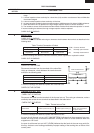
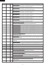
Table: Terminal Connection of Switch
Plunger Operation COM to NO COM to NC COM; Common terminal
Released Open circuit Short circuit NO; Normally open terminal
Depressed Short circuit Open circuit NC; Normally close terminal
If incorrect readings are obtained, make the necessary switch adjustment or replace the switch.
CARRY OUT
4R CHECKS.
F NOISE FILTER TEST
CARRY OUT 3D CHECKS.
Disconnect the leads from the terminals of the noise filter.
Using an ohmmeter, check between the terminals as de-
scribed in the following table.
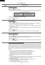
MEASURING POINT INDICATION OF OHMMETER
Between N and L Open circuit
Between terminal N and WHITE Short circuit
Between terminal L and RED Short circuit
If incorrect readings are obtained, replace the noise filter unit.
CARRY OUT 4R CHECKS.
CARRY OUT 3D CHECKS.
Disconnect the leads from the terminals of the thermal cut-out. Then using an ohmmeter, make a
continuity test across the two terminals as described in the table below.
CARRY OUT 4R CHECKS.
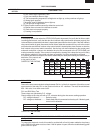
Table: Thermal cut-out Test
Temperature of "ON" Temperature of "OFF" Indication of ohmmeter
Parts Name condition (closed circuit) (˚C) condition (open circuit) (˚C) (When room temperature
is approx. 20˚C)
Thermal cut-out 145˚C This is not resetable type. Above 145˚C Closed circuit.
If incorrect readings are obtained, replace the thermal cut-out.
An open circuit thermal cut-out 145˚C (MAGNETRON) indicates that the magnetron has over-
heated, this may be due to restricted ventilation, cooling fan failure or a fault condition within the
magnetron or HV circuit.
An open circuit thermal cut-out 145˚C (OVEN) indicates that the foods in the oven may catch fire,
this may be due to over heating produced by improper setting of the cooking time or failure of the
control panel.
G THERMAL CUT-OUT TEST
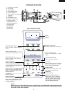
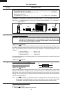
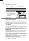
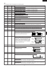
FUSE
F10A
NOISE SUPPRESSION COIL
NL
0.0022µ/AC 250V
0.0022µ/AC 250V
LINE CROSS CAPACITOR
0.068µ/AC250V
WHT RED