


R-480J
20
SW1
SW2
SW3
SW4
SW5
P20
P21
P22
P23
P24
LSI
(IC1)
AIN4
AIN5
620k
300k
150k
75k
37.4k
26
23
22
50
49
24
25
15k
15k
4.7k
1234
8765
0.01uF
0.1uF
0.01uF
VA : -15V
VA : -15V
R90
330
C90
C91
C93
C92
S
F-2
1.8k
IC2
F-1
F-3
C
3.57k
3.32k
VC : -5V
0.1
uF
C. Thermistor in
closed vessel
S. Thermistor in
open vessel
R98
R99
R96
R91
360k
R93
R92
R94
R95
D90
R100
R101
R102
R97
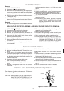
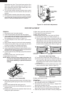
ABSOLUTE HUMIDITY SENSOR CIRCUIT
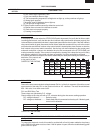
(1) Structure of Absolute Humidity Sensor
The absolute humidity sensor includes two thermistors
as shown in the illustration. One thermistor is housed
in the closed vessel filled with dry air while another in
the open vessel. Each sensor is provided with the
protective cover made of metal mesh to be protected
from the external airflow.
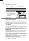
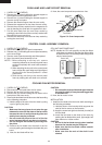
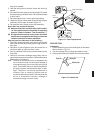
(2) Operational Principle of Absolute Humidity Sensor
The figure below shows the basic structure of an
absolute humidity sensor. A bridge circuit is formed by
two thermistors and two resistors (R1 and R2).
The output of the bridge circuit is to be amplified by the
operational amplifier.
Each thermistor is supplied with a current to keep it
heated at about 150˚C (302˚F), the resultant heat is
dissipated in the air and if the two thermistors are
placed in different humidity conditions they show
different degrees of heat conductivity leading to a
potential difference between them causing an output
voltage from the bridge circuit, the intensity of which is
increased as the absolute humidity of the air increases.
Since the output is very minute, it is amplified by the
operational amplifier.
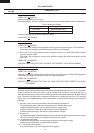
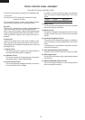
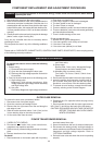
(3) Detector Circuit of Absolute Humidity Sensor Circuit
This detector circuit is used to detect the output voltage
of the absolute humidity circuit to allow the LSI to
control sensor cooking of the unit. When the unit is set
in the sensor cooking mode, 16 seconds clearing cycle
occurs than the detector circuit starts to function and
the LSI observes the initial voltage available at its AIN5
terminal.
With this voltage given, the switches SW1 to SW5 in
the LSI are turned on in such a way as to change the
resistance values in parallel with R98 ~ R102. Changing
the resistance values results in that there is the same
potential at both F-3 terminal of the absolute humidity
sensor and AIN4 terminal of the LSI. The voltage of
AIN5 terminal will indicate about -2.5V. This initial
balancing is set up about 16 seconds after the unit is
put in the Sensor Cooking mode. As the sensor
cooking proceeds, the food is heated to generate
moisture by which the resistance balance of the bridge
circuit is deviated to increase the voltage available at
AIN5 terminal of the LSI.
Then the LSI observes that voltage at AIN5 terminal
and compares it with its initial value, and when the
comparison rate reaches the preset value (fixed for
each menu to be cooked), the LSI causes the unit to
stop sensor cooking; thereafter, the unit goes in the
next operation automatically.
When the LSI starts to detect the initial voltage at AIN5
terminal 16 seconds after the unit has been put in the
Sensor Cooking mode, if it is not possible to balance
the bridge circuit due to disconnection of the absolute
humidity sensor, ERROR will appear on the display
and the cooking is stopped.
1) Absolute humidity sensor circuit
ventilation opening for sensing
Sensing part
(Open vessel)
Sensing part
(Closed vessel)
Thermistors
C
S
R3
R1
R2
+
Operational
amplifier
Output
voltage
S : Thermistor
open vessel
C : Thermistor
closed vessel
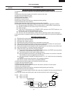
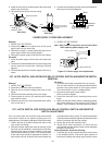
2
Absolute humidity (g/m )
Output voltage
Absolute humidity vs,
output voltage characteristic