


R-480J
25
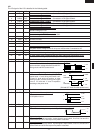
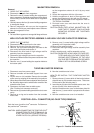
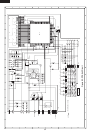
2. Install the fan motor to the back plate of the oven cavity
with the two (2) screws.
3. Re-install the fan duct to the oven cavity.
4. Connect the wire leads to the fan motor and magnetron,
referring to the pictorial diagram.
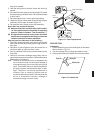
Rear View
Side View
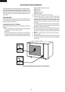
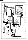
POWER SUPPLY CORD REPLACEMENT
Removal
1. CARRY OUT 3D CHECKS.
2. Disconnect the brown and blue wires of the power
supply cord from the noise filter.
3. Remove the single (1) screw holding the earth wire of
power supply cord to the chassis support.
4. Remove the power supply cord from the rear cabinet.
Re-install
1. Insert the power supply cord into the oven cavity back
plate.
2. Connect the brown and blue wires of power supply cord
into the terminals of noise filter, referring to pictorial
diagram.
3. Re-install the earth wire to chassis support with one (1)
screw.
4. CARRY OUT 4R CHECKS.
Note : Step 4 above is important, and it must be done
after replacing power supply cord.
Removal
1. CARRY OUT 3D CHECKS.
2. Disconnect wire leads from the switches.
3. Remove two (2) screws holding latch hook to oven
flange.
4. Remove latch hook assembly from oven flange.
5. Push outward on the two (2) retaining tabs holding
each switch in place.
6. Switches are now free. At this time switch lever will be
free, do not lose it.
Re-install
1. Re-install each switch and switch lever in its place.
The 1st. latch switch is in the lower position and 2nd.
interlock relay control switch is in the upper position.
The monitor switch is in the middle position.
2. Re-connect wire leads to each switch.
Refer to pictorial diagram.
3.
Secure latch hook (with two (2) mounting screws) to oven
flange.
4. Make sure that the monitor switch is operating properly
and check continuity of the monitor circuit. Refer to
chapter "Test Procedure" and Adjustment procedure.
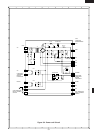
1ST. LATCH SWITCH, 2ND. INTERLOCK RELAY CONTROL SWITCH AND MONITOR SWITCH
REMOVAL
1ST. LATCH SWITCH, 2ND. INTERLOCK RELAY CONTROL SWITCH AND MONITOR
SWITCH ADJUSTMENT
If the 1st. latch switch, 2nd. interlock relay control switch
and monitor switch do not operate properly due to a
misadjustment, the following adjustment should be made.
1. Loosen the two (2) screws holding latch hook to the
oven cavity front flange.
2. With door closed, adjust latch hook by moving it back
and forth, and up and down. In and out play of the door
allowed by the upper and lower position of the latch
hook should be less than 0.5mm. The vertical position
of the latch hook should be adjusted so that the 1st.
latch switch and 2nd. interlock relay control switch are
activated with the door closed. The holizontal position
of the latch hook should be adjusted so that the monitor
switch is activated with the door closed.
3. Secure the screws with washers firmly.
4. Check the all switch operation. If a switch has not
activated with the door closed, loosen screw and adjust
the latch hook position.
After adjustment, check the following.
1. In and out play of door remains less than 0.5mm when
in the latched position. First check upper position of
latch hook, pushing and pulling upper portion of door
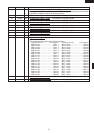
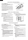
Figure C-4. Power supply cord replacement
Noise filter
Power supply cord
Brown wire
Blue wire
Green/Yellow wire
N
L
WHT
RED
M10A
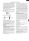
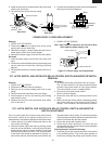
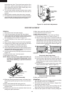
Gap
Rotor
Bracket
Stator
Groove joint pliers
Coil
Shaft
Axis
Stator
Rotor
These are the positions
that should be pinched
with pliers.
Shaft
Table
Center of
bracket