


R-480J
23
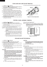
Removal
1. CARRY OUT 3D CHECKS.
2. Disconnect wire leads from magnetron.
3. Remove the two (2) screws holding the magnetron air
duct to magnetron. And slide magnetron air duct slightly
so that two (2) screws at left hand side of magnetron
appear.
4. Carefully remove the four (4) screws holding magnetron
to waveguide flange.
5. Remove magnetron with care so that magnetron
antenna is not hit by any metal object around antenna.
6. Now, the magnetron is free.
Re-install
1. Re-install the magnetron to waveguide flange with care
MAGNETRON REMOVAL
so that magnetron antenna is not hit by any metal
object.
2. Secure the magnetron with four (4) screws.
3. Hold the magnetron air duct to the magnetron and
secure the magnetron air duct with two (2) screws.
4. Re-connect the wire leads to the magnetron. Refer to
"PICTORIAL DIAGRAM".
5. Re-install outer case and check that the oven is
operating properly.
CAUTION: WHEN REPLACING MAGNETRON, BE
SURE THE R.F. GASKET IS IN PLACE AND
MOUNTING SCREWS ARE TIGHTENED
SECURELY
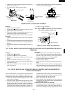
1. CARRY OUT
3D CHECKS.
2. Disconnect the wire lead from the fan motor.
3. Remove the fan duct from the oven cavity.
4. Remove two (2) screws holding the fan motor to the
oven cavity back plate and remove it.
5. Disconnect the wire lead of high voltage rectifier
assembly from the magnetron.
6. Disconnect high voltage fuse from the capacitor.
7. Disconnect filament lead of the power transformer from
the capacitor.
8. Remove one (1) screw holding the capacitor holder to
the bottom plate.
9. Remove one (1) screw holding high voltage rectifier
assembly to the capacitor holder.
10.Remove the capacitor holder
11.Disconnect the high voltage rectifier assembly from
capacitor.
12.Now, capacitor and rectifier assembly are free.
CAUTION: WHEN REPLACING HIGH VOLTAGE REC-
TIFIER AND HIGH VOLTAGE CAPACITOR,
GROUND SIDE TERMINAL OF THE HIGH
VOLTAGE RECTIFIER MUST BE SECURED
FIRMLY WITH A GROUNDING SCREW.
HIGH VOLTAGE RECTIFIER ASSEMBLY AND HIGH VOLTAGE CAPACITOR REMOVAL
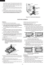
TURNTABLE MOTOR REMOVAL
1. Disconnect oven from power supply.
2. Remove turntable and turntable support from oven
cavity.
3. Lay the oven on it's backside. Remove the turntable
motor cover by snipping off the material in four portions.
4. Where the portions have been snipped off bend portions
flat. No sharp edge must be evident after removal of the
turntable motor cover.
5. Disconnect wire leads from turntable motor.
(See "Positive lock connector removal")
6. Remove two (2) screws holding turntable motor to oven
cavity.
7. Remove an o-ring and a washer from the turntable
motor shaft.
8. Now the turntable motor is free.
HOW TO RE-INSTALL THE TURNTABLE MOTOR
COVER
1. Remove the one (1) screw which is fixed on the bottom
plate left near by the turntable motor cover. This screw
will be used at the following step 3.
2. Insert the two (2) tabs of the turntable motor cover into
the two (2) slits of the bottom plate left.
3. Hold the turntable motor cover to the bottom plate left
with the one (1) screw which is prepared at the above
step 1.
4. Now the turntable motor cover is re-installed.
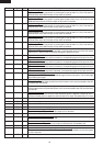
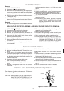
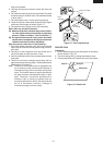
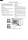
Push the lever of positive lock
®
connector. Pull down on
the positive lock
®
connector.
CAUTION: WHEN CONNECTING THE POSITIVE LOCK
®
CONNECTORS TO THE TERMINALS, IN-
STALL THE POSITIVE LOCK
®
SO THAT THE
LEVER FACES YOU (SERVICE PERSON).
POSITIVE LOCK
®
CONNECTOR (NO-CASE TYPE) REMOVAL
Figure C-1 Positive lock
®
connector
Terminal
Push
Pull down
1
2
Lever
Positive lock®
connector