


R-480J
17
LSI
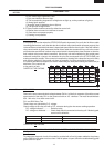
The I/O signal of the LSI is detailed in the following table.
Pin No. Signal I/O Description
1 COM5 OUT Common data signal : COM11. Connected to LCD signal COM11.
2 COM4 OUT
Common data signal : COM12. Connected to LCD signal COM12.
3 COM3 OUT Common data signal : COM13. Connected to LCD signal COM13.
4 COM2 OUT Common data signal : COM14. Connected to LCD signal COM14.
5 COM1 OUT Common data signal : COM15. Connected to LCD signal COM15.
6 COM0 OUT Common data signal : COM16. Connected to LCD signal COM16.
7-10 VL1-VL4 IN
Power source voltage input terminal.
Standard voltage for LCD.
11 VL5 IN
Power source voltage input terminal.
Standard voltage for LCD. Connected to GND.
12-14 C3-C1 IN Terminal not used.
15 VLIN IN Terminal not used.
16 VREG OUT Terminal not used.
17 NC
_
Terminal not used.
18 VSS IN
Power source voltage : -5.0V.
The power source voltage to the LSI is input to VSS terminal. Connected to VC.
19-21 P27-P25 OUT Terminal not used.
22-26 P24-P22 IN Used for initial balancing of the bridge circuit (absolute humidity sensor).
27 P47 IN
To input signal which communicates the door open/close information to LSI.
Door close "H" level signal (0V). Door open "L" level signal (-5V).
28 P46 OUT Terminal not used.
29 P45 OUT
Oven lamp, fan motor and turntable motor driving signal.
To turn on and off shut off relay (RY1). The
square waveform voltage is delivered to the RY1
driving circuit and RY2 control circuit.
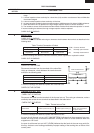
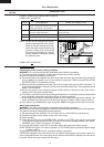
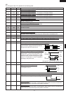
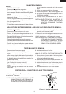
30 P44 OUT Magnetron high-voltage circuit driving signal.
To turn on and off the cook relay (RY2). The
signals holds "L" level during microwave cook-
ing and "H" level while not cooking. In other
cooking modes (variable cooking) the signal
turns to "H" level and "L" level in repetition
according to the power level.
(ON and OFF times for other power level.)
31 P43
_
Terminal not used.
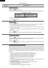
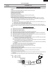
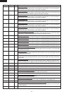
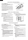
32 CNTR0 OUT
Signal to sound buzzer (2.0 kHz).
A: key touch sound.
B: Completion sound.
33 P41 OUT Terminal not used.
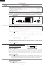
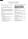
34 INT0 IN
Signal synchronized with commercial power source frequency.
This is the basic timing for time processing of LSI.
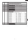
35 P07 OUT Key strobe signal.
Signal applied to touch-key section. A pulse signal is input to AIN7, P14, P15, P16 and P17
terminal while one of G1 line keys on key matrix is touched.
36 P06 OUT
Key strobe signal.
Signal applied to touch-key section. A pulse signal is input to AIN7, P14, P15, P16 and P17
terminal while one of G2 line keys on key matrix is touched.
20.0 msec.
During cooking
H : GND
L : -5V
100
PERCENT
70
PERCENT
H : GND
L : -5V
H : GND
L : -5V
ON
ON
OFF
OFF OFF
24 sec.
8 sec.
20.0 msec.
H : GND
L : -5V
A
B
0.1 sec.
2.0 sec.
H : GND
L : -5V
H : GND
L : -5V