


R-480J
4
OPERATION SEQUENCE
because the relay (RY1) stays closed. Shown in the
display is the remaining time.
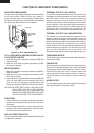
6. MONITOR SWITCH CIRCUIT
The monitor switch is mechanically controlled by oven
door, and monitors the operation of the 1st. latch switch
and 2nd. interlock relay.
6-1 When the oven door is opened during or after the
cycle of a cooking program, the 1st. latch switch and
2nd. interlock relay control switch must open their
contacts first. After that the contacts (COM-NC) of the
monitor switch can be closed.
6-2. When the oven door is closed, the contacts (COM-
NC) of the monitor switch must be opened first. After
that the contacts of the 1st. latch switch and 2nd.
interlock relay control switch are closed.
6-3. When the oven door is opened and the contacts of the
1st. latch switch and 2nd. interlock relay remain
closed. The fuse F10A will blow, because the monitor
switch is closed and a short circuit is caused.
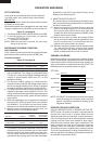
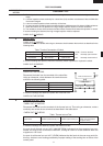
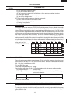
VARIABLE COOKING
When the microwave oven is preset for variable cooking
power. Rated voltage is supplied to the power transformer
intermittently within a 32-second time base through the
relay contact which is coupled with the relay (RY2). The
following levels of microwave power are given.
SETTING;
OFF CONDITION
Closing the door activates all door interlock switches
(1st. latch switch, 2nd. interlock relay control switch)
IMPORTANT
When the oven door is closed, the monitor switch contacts
(COM-NC) must be open.
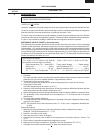
When the microwave oven is plugged in a wall outlet, rated
voltage is supplied to the noise filter and the control unit.
Figure O-1 on page 29
1. The display shows SHARP, MICRO-WAVE and OVEN.
2. To set any programs or set the clock, you must first
touch the STOP/CLEAR pad.
3. “ : “ appears in the display.
NOTE: When the oven door is opened, the oven lamp
comes on at this time.
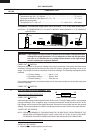
MICROWAVE COOKING CONDITION
HIGH COOKING
Enter a desired cooking time with the touching Number
pads and start the oven with touching START pad.
Function sequence
Figure O-2 on page 29
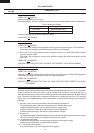
CONNECTED COMPONENTS RELAY
Oven lamp, Fan motor, Turntable motor RY1
Power transformer RY2
1. Rated voltage is supplied to the primary winding of the
power transformer. The voltage is converted to about
3.3 volts A.C. output on the filament winding and high
voltage of approximately 2000 volts A.C. on the
secondary winding.
2. The filament winding voltage (3.3 volts) heats the
magnetron filament and the high voltage (2000 volts) is
sent to the voltage doubling circuit, where it is doubled
to negative voltage of approximately 4000 volts D.C..
3. The 2450 MHz microwave energy produced in the
magnetron generates a wave length of 12.24 cm. This
energy is channelled through the waveguide (transport
channel) into the oven cavity, where the food is placed
to be cooked.
4. When the cooking time is up, a signal tone is heard and
the relays (RY1+RY2) go back to their home position
(off condition)º. The circuits to the oven lamp, power
transformer, fan motor and turntable motor are cut off.
5. When the door is opened during a cook cycle, the
switches come to the following condition
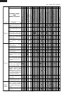
CONDITION
DURING DOOR OPEN
SWITCH CONTACT COOKING
(NO COOKING)
1st. latch switch COM-NO Closed Open
2nd. interlock relay
control switch COM-NO Closed Open
Monitor switch COM-NC Open Closed
The circuits to the power transformer, fan motor and
turntable motor are cut off when the 1st. latch switch
and 2nd. interlock relay control switch are made open.
The oven lamp remains on even if the oven door is
opened after the cooking cycle has been interrupted,
NOTE: The ON/OFF time ratio does not exactly correspond
to the percentage of microwave power, because
approx. 3 seconds are needed for heating up the
magnetron filament.
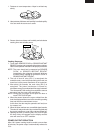
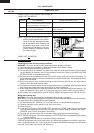
SENSOR COOKING CONDITION
Using the SENSOR COOK or SENSOR INSTANT RE-
HEAT function, the foods are cooked or reheated without
figuring time, power level or quantity. When the oven
senses enough steam from the food, it relays the informa-
tion to its microprocessor which will calculate the remaining
cooking time and power level needed for best results.
When the food is cooked, water vapor is developed. The
sensor “senses” the vapor and its resistance increases
gradually. When the resistance reaches the value set
according to the menu, supplementary cooking is started.
The time of supplementary cooking is determined by ex-
periment with each food category and inputted into the LSI.
An example of how sensor works:
HIGH
32 sec. ON
MEDIUM HIGH Approx. 70%
24 sec. ON 8 sec. OFF
14 sec. OFF
20 sec. OFF
26 sec. OFF
MEDIUM Approx. 50%
18 sec. ON
MEDIUM LOW Approx. 30%
12 sec. ON
LOW Approx. 10%
6 sec. ON