


R-480J
24
OVEN LAMP AND LAMP SOCKET REMOVAL
1. CARRY OUT 3D CHECKS.
2. Remove one (1) screw holding the chassis support to
the magnetron and magnetron air duct.
3. Remove one (1) screw holding the chassis support to
the oven cavity front plate.
4. Remove the chassis support from the oven cavity.
5. Release the magnetron air duct from the oven cavity.
6. Remove the oven lamp socket from the magnetron air
duct by bending the small tab of magnetron air duct.
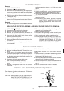
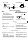
7. Pull the wire leads from the oven lamp socket by
pushing the terminal hole of the oven lamp socket with
the small flat type screw driver.
8. Remove the oven lamp from the oven lamp socket by
turning the oven lamp.
9. Now, the oven lamp and lamp socket are free.
CONTROL PANEL ASSEMBLY REMOVAL
1. CARRY OUT 3D CHECKS.
2. Disconnect wire leads from panel components.
3. Release one (1) nail holding the control panel assembly
to the oven flange.
4. Remove control panel assembly and slide upward.
5. Now, the control panel assembly is free.
NOTE: 1. Before attaching a new key unit, remove
remaining adhesive on the control panel frame
surfaces completely with a soft cloth soaked in
alcohol.
2. When attaching the key unit to the control panel
frame, adjust the upper edge and right edge of
the key unit to the correct position of control
panel frame.
3. Stick the key unit firmly to the control panel
frame by rubbing with soft cloth not to scratch.
CPU UNIT AND POWER UNIT
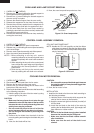
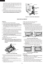
NOTE: Handle the CPU unit carefully so that the ribbon
cable does not come off. Because the ribbon cable
is sticked on the LCD and the printed wiring board
only by heated paste.
1. CARRY OUT 3D CHECKS.
2. Disconnect the wire leads from the fan motor.
3. Remove the fan duct from the oven cavity.
4. Remove two (2) screws holding the fan motor to the
back plate of the oven cavity.
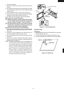
5. Remove the fan blade from the fan motor shaft according
to the following procedure.
1) Hold the edge of the rotor of the fan motor by using
a pair of grove joint pliers.
CAUTION:
* Make sure that any pieces do not enter the gap
between the rotor and the stator of the fan motor
because the rotor is easily shaven by pliers and
metal pieces may be produced.
* Do not touch the pliers to the coil of the fan
motor because the coil may be cut or injured.
*Do not disfigure the bracket by touching with
the pliers.
2) Remove the fan blade from the shaft of the fan
motor by pulling and rotating the fan blade with your
hand.
3) Now, the fan blade will be free.
CAUTION:
* Do not use this removed fan blade again because
the hole (for shaft) of it may become bigger than
a standard one.
6. Now, the fan motor is free.
INSTALLATION
1. Install the fan blade to the fan motor shaft according to
the following procedure.
1) Hold the center of the bracket which supports the
shaft of the fan motor on the flat table.
2) Apply the screw lock tight into the hole (for shaft) of
the fan blade.
3) Install the fan blade to the shaft of fan motor by
pushing the fan blade with a small, light weight, ball
peen hammer or rubber mallet.
CAUTION:
* Do not hit the fan blade strongly when installed
because the bracket may be disfigured.
* Make sure that the fan blade rotates smooth
after installation.
* Make sure that the axis of the shaft is not
slanted.
COOLING FAN MOTOR REMOVAL
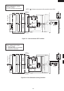
Figure C-2. Oven lamp socket
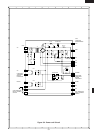
Figure C-3 CPU unit
Oven lamp
socket
Terminal
Wire lead
Terminal hole
Flat type small
screw driver
Printed wiring board
of CPU unit
Liquid Crystal
Display (LCD)
Ribbon cable