


R-480J
18
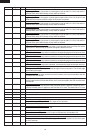
37 P05 OUT
Key strobe signal.
Signal applied to touch-key section. A pulse signal is input to AIN7, P14, P15, P16 and P17
terminal while one of G3 line keys on key matrix is touched.
38 P04 OUT
Key strobe signal.
Signal applied to touch-key section. A pulse signal is input to AIN7, P14, P15, P16, P17 and
AIN6 terminal while one of G4 line keys on key matrix is touched.
39 P03 OUT
Key strobe signal.
Signal applied to touch-key section. A pulse signal is input to AIN7, P14, P15, P16 and P17
terminal while one of G5 line keys on key matrix is touched.
40 P02 OUT
Key strobe signal.
Signal applied to touch-key section. A pulse signal is input to AIN7, P14, P15, P16 and P17
terminal while one of G6 line keys on key matrix is touched.
41 P01 OUT
Key strobe signal.
Signal applied to touch-key section. A pulse signal is input to AIN7, P14, P15, P16 and P17
terminal while one of G7 line keys on key matrix is touched.
42 P00 OUT
Key strobe signal.
Signal applied to touch-key section. A pulse signal is input to AIN7, P14, P15, P16 and P17
terminal while one of G8 line keys on key matrix is touched.
43 P17 IN
Signal coming from touch key.
When either G9 line on key matrix is touched, a corresponding signal out of P00-P07 will be
input into P17. When no key is touched, the signal is held at "H" level.
44 P16 IN
Signal similar to P17.
When either G10 line on key matrix is touched, a corresponding signal will be input into P16.
45 P15 IN
Signal similar to P17.
When either G11 line on key matrix is touched, a corresponding signal will be input into P15.
46 P14 IN
Signal similar to P17.
When either G12 line on key matrix is touched, a corresponding signal will be input into P14.
47 AIN7 IN
Signal similar to P17.
When either G13 line on key matrix is touched, a corresponding signal will be input into AIN7.
48 AIN6 IN
Input terminal to judge the model.
The signal out of P04 will be input into AIN6 through G4 line on key matrix. The LSI will judge
the model by this signal.
49 AIN5 IN
AH sensor input.
This input is an analog input terminal from the AH sensor circuit, and connected to the A/D
converter built into the LSI.
50 AIN4 IN Used for initial balancing of the bridge circuit (absolute humidity sensor). This input is an
analog input terminal from the AH sensor circuit, and connected to the A/D converter built
into the LSI.
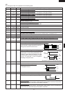
51 RESET IN
Auto clear terminal.
Signal is input to reset the LSI to the initial state when power is applied. Temporarily set "L"
level the moment power is applied, at this time the LSI is reset. Thereafter set at "H" level
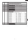
52 NC
_
Terminal not used.
53 XCOUT OUT Terminal not used.
54 XCIN IN Connected to VC.
55 NC
_
Terminal not used.
56 VCC IN
Power source voltage: GND(0V).
The power source voltage to drive LSI is input to VCC terminal.
57 OSCSEL IN Connected to VC(-5V).
58 XOUT OUT
Internal clock oscillation output.
Output to control oscillation input of XIN.
59 VSS IN
Power source voltage: -5.0V.
The power source voltage to the LSI is input to VSS terminal. Connected to VC.
60 NC
_
Terminal not used.
61 XIN IN
Internal clock oscillation frequency control input setting.
The internal clock frequency is set by inserting the ceramic filter oscillation circuit with respect
to XOUT terminal.
62 NC
_
Terminal not used.
Pin No. Signal I/O Description