


R-480J
12
K TOUCH CONTROL PANEL ASSEMBLY TEST
TEST PROCEDURES
PROCEDURE
LETTER
COMPONENT TEST
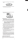
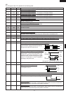
H MOTOR WINDING TEST
CARRY OUT 3D CHECKS.
Disconnect the leads from the motor.
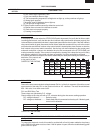
Using an ohmmeter, check the resistance between the two terminals as described in the table below.
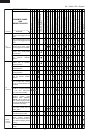
Table: Resistance of Motor
Motors Resistance
Fan motor Approximately 250 Ω
Turntable motor Approximately 14.5 kΩ
If incorrect readings are obtained, replace the motor.
CARRY OUT 4R CHECKS.
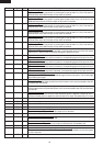
CARRY OUT 3D CHECKS.
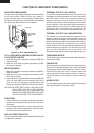
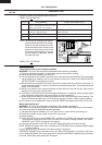
1. If the fuse F10A is blown, there could be shorts or ground in electrical parts or wire harness.
Check them and replace the defective parts or repair the wire harness.
2. If the fuse F10A is blown when the door is opened, check the 1st. latch switch, 2nd. interlock
relay and monitor switch.
If the fuse F10A is blown by incorrect door switching replace the defective switch(s) and the
fuse F10A.
CARRY OUT 4R CHECKS.
CAUTION: ONLY REPLACE FUSE F10A WITH THE CORRECT VALUE REPLACEMENT
I BLOWN FUSE F10A
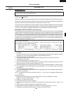
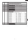
The touch control panel consists of circuits including semiconductors such as LSI, ICs, etc. Therefore,
unlike conventional microwave ovens, proper maintenance cannot be performed with only a
voltmeter and ohmmeter. In this service manual, the touch control panel assembly is divided into two
units, Control Unit and Key Unit, and also the Control Unit is divided into two units, CPU Unit and
Power Unit, and troubleshooting by unit replacement is described according to the symptoms
indicated.
1. Key Unit. Note: Check key unit ribbon connection before replacement.
The following symptoms indicate a defective key unit. Replace the key unit.
a) When touching the pads, a certain pad produces no signal at all.
b) When touching a number pad, two figures or more are displayed.
c) When touching the pads, sometimes a pad produces no signal.
2. Control Unit.
The following symptoms indicate a defective control unit. Before replacing the control unit, perform
the Key unit test (Procedure L) to determine if control unit is faulty.
2-1 In connection with pads.
a) When touching the pads, a certain group of pads do not produce a signal.
b) When touching the pads, no pads produce a signal.
2-2 In connection with indicators.
a) At a certain digit, all or some segments do not light up.
J HIGH VOLTAGE FUSE TEST
CARRY OUT 3D CHECKS.
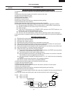
If the high voltage fuse is blown, there could be a short in the high voltage rectifier or the magnetron.
Check them and replace the defective parts and high voltage fuse.
CARRY OUT 4R CHECKS.
CAUTION: ONLY REPLACE THE HIGH VOLTAGE FUSE WITH THE CORRECT VALUE RE-
PLACEMENT