


23
Models 336, 338 & 339 Operating Procedures
Cleaning
Step 1
Prepare a pail of approved 100 PPM cleaning solution
(examples: 2--1/2 gal. [9.5 liters] of Kay--5R or 2 gal.
[7.6 liters] of Stera--SheenR). USE WARM WATER
AND FOLLOW THE MANUFACTURER’S SPECIFIC-
ATIONS.
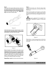
Step 2
Push down the prime plug. Pour the cleaning solution
into the mix hopper.
Step 3
While the solution is flowing into the freezing cylinder,
brush clean the mix hopper, mix level sensing probe,
and the mix inlet hole.
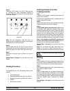
Step 4
Press the “WASH” button. This will cause the cleaning
solution in the freezing cylinder to agitate.
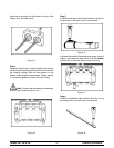
Step 5
Place an empty pail beneath the door spout and raise
the prime plug.
Step 6
When a steady stream of cleaning solution is flowing
from the prime plug opening in the bottom of the
freezer door, lower the draw handle. Draw off all of the
solution.
Step 7
Once the cleaner stops flowing from the door spout,
raise the draw handle and press the “WASH” button,
cancelling the “WASH” mode.
Repeat Steps 1 through 7 for the other side of the
freezer.
Disassembly
Step 1
BE SURE THE POWER SWITCH IS IN THE
“OFF” POSITION. MAKE SURE NO LIGHTS ARE
LIT ON THE CONTROL PANEL.
Step 2
Remove the handscrews, freezer door, beaters,
scraper blades, and drive shafts from the freezing
cylinders. Ta ke these parts to the sink for cleaning.
Step 3
Remove the front drip tray and the splash shield.
Brush Cleaning
Step 1
Prepare a sink with a n approved cleaning solution
(examples: Kay--5R or Stera--S heenR). USE WARM
W ATER AND FOLLOW THE MANUFACTURER’S
SPECIFICATIONS. If another approved cleaner is
used, dilute it according to the label instructions.
(IMPORTANT: Follow the label directions. Too
STRONG of a solution can cause parts damage, while
too MILD of a solution will not provide adequate
cleaning.) Make sure all brushes pr ovided with the
freezer are available for brush cleaning.
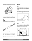
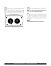
Step 2
Remove the seals from the drive shafts.
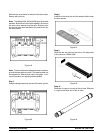
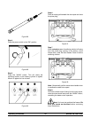
Step 3
From the freezer door remove:
S gaskets
S front bearings
S pivot pins
S adjustable draw handles
S design caps
S draw valves
S prime plugs
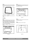
Remove all o--rings.
Note: To remove o--rings, use a single service towel
to grasp the o--ring. Apply pressure in an upward
direction until the o--r ing pops out of its groove. With
the other hand, push the top of the o--ring forward and
it will roll out of the groove and can b e easily removed.
If there is more than one o--ring to be removed, always
remove the rear o--r ing first. This will allow the o--ring
to slide over the forward rings without falling into the
open grooves.