


33
Models 8752 & 8756 with Horizon® Pump Operating Procedures
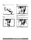
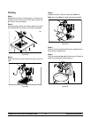
Step 5
Place an empty pail beneath the door spout, r aise the
prime plug, and press the WASH and PUMP keys.
Step 6
When a steady stream of solution is flowing from the
prime plug hole in the bottom of the freezer door, pull
down the draw handle and draw off the remaining
cleaning solution.
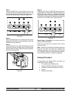
Step 7
Once the solution stops flowing from the door spout,
close the draw valve and press the W ASH and PUMP
keys to stop operation.
Repeat Steps 1 through 7 for the other side of the
freezer on the Model 8756.
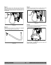
Step 8
Place the power switch in the OFF position before
disassembling the machine.
Disassembly
Step 1
BE SURE THE POWER SWITCH IS IN THE “OFF”
POSITION. CHECK TO MAKE SURE NO LIGHTS
ARE ILLUMINATED ON THE CONTROL PANE L.
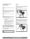
Step 2
Remove the handscrews, freezer door , beater, shoes,
scraper blades and drive shaft from the freezing
cylinder, and take them to the sink for cleaning.
Step 3
Remove the air line and the pressure line from their
connections.
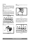
Step 4
Remove the check valve assembly from the pressure
switch cap.
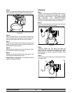
Step 5
Remove the pressure switch cap from the mix cabinet
and the remove the diaphragm from the cap.
Step 6
Disassemble the check valve.
Step 7
Remove the pressure relief valve and disassemble.
Repeat Steps 2 through 7 for the other side of the
freezer on the Model 8756.
Step 8
Remove the front drip tray and s plash shield.
Brush Cleaning
Step 1
Prepare a sink with an approved cleaning solution
(examples: Kay--5R or Stera--SheenR). USE WARM
W ATER AND FOLLOW THE MANUFACTURER’S
SPECIFICATIONS.
IMPORTANT: Follow the label directions. Too
STRONG of a solution can cause parts damage, while
too MILD of a solution will not provide adequate
cleaning. Make sure all brushes provided with the
freezer are available for br ush cleaning.
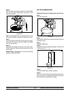
Step 2
Remove the seal(s) from the drive shaft(s).
Step 3
Remove the scraper blade clips from the scraper
blades.
Step 4
From the freezer door(s) remove the gasket(s), front
bearing(s), pivot pin(s), draw handle(s), draw valve(s),
prime plug(s), and the design cap(s).
Step 5
Remove the flare line(s), suction line( s), a ir line(s)
pressure line(s), relief assembly(s), and check
valve(s).
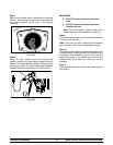
Step 6
Disassemble all parts and remove the o--rings.
Note: To remove o--rings, use a single service towel
to grasp the o--ring. Apply pressure in an upward
direction until the o--ring pops out of its groove. With
the other hand, push the top of the o--ring forward. It
will roll out of the groove and can be easily removed.
If there is more than one o--ring to be removed, always
remove the rear o--ring first. This will allow the o--ring
to slide over the forward rings without falling into the
open grooves.