


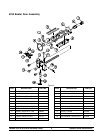
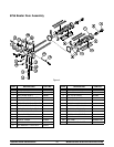
2
Models 8752 & 8756 with Horizon® PumpTo the Installer
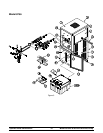
Water Connections
(Water Cooled Units Only)
An adequate cold water supply must be provided with
a hand shut--off valve. On the underside rear of the
base pan, two 3/8” I.P.S. (for single--head units) or two
1/2” I.P.S. (for double--head units) water connections
for inlet and outlet have been provided for easy
hook--up. 1/2” inside diameter water lines should be
connected to the machine. (Flexible lines are
recommended, if local codes permit.) Depending on
local water conditions, i t may be advisable to i nstall a
water strainer to prevent foreign substances from
clogging the automatic water valve. There will be only
one water “in” and one water “out” connection for both
single--head and double--head units. DO NOT install a
hand shut--off valve on the water “out” line! Water
should always flow in this order: first, through the
automatic water valve; second, through t he
condenser; and third, through the outlet fitting to an
opentrapdrain.
A back flow prevention device is required
on the incoming water connection side. Please
refer to the applicable National, State, and local codes
for determining the proper configuration.
Electrical Connections
In the United States, this equipment is intended to be
installed in a ccordance with the National Electrical
Code (NEC), A NSI/NFPA 70--1987. The pur pose of
the NEC code is the practical safeguarding of persons
and property from hazards arising from the use of
electricity. This code contains provisions considered
necessary for safety. Com pliance therewith and
proper maintenance will result in an installation
essentially free from hazard!
In all other areas of the world, equipment should be
installed in accordance with the existing local codes.
Please contact your local authorities.
FOLLOW YOUR LOCAL ELECTRICAL CODES!
Each freezer requires one power supply for each data
label. Check the data label(s) on the freezer for branch
circuit overcurrent protection or fuse, circuit ampacity,
and electrical specifications. Refer to the wiring
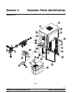
diagram provided inside the c ontrol box for proper
power connections.
CAUTION: THIS EQUIPMENT MUST BE
PROPERLY GROUNDED! FAILURE TO DO SO
CAN RESULT IN SEVERE PERSONAL INJURY
FROM ELECTRICAL SHOCK!
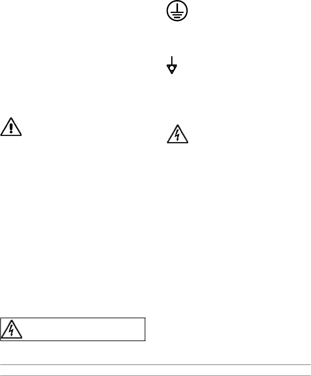
This unit is provided with an equipotential
grounding lug that is to be properly attached to the rear
of the frame by the authorized installer . The installation
location is marked by the equipotential bonding
symbol (5021 of IEC 60417-1) on both the removable
panel and the equipment’s frame.
S Stationary appliances which are not
equipped with a power c ord and a plug or
another device to disconnect the appliance
from the power s ource must have an all-pole
disconnecting device with a contact gap of
at least 3 mm installed in the external
installation.
S Appliances that are permanently connected
to fixed wiring and for which leakage
currents may exceed 10 mA, particularly
when disconnected or not used for long
periods, or during initial installation, shall
have protective devices such as a GFI, to
protect against the leakage of current and
be installed by the authorized personnel to
the local c odes.
S Supply cords used with this unit shall be
oil-resistant, sheathed flexible cable not
lighter than ordinary polychloroprene or
other equivalent synthetic
elastomer-sheathed cord (Code designation
60245 IEC 57) installed with the proper cord
anchorage to relieve conductors from strain,
including twisting, at the terminals and
protect the insulation of the conductors from
abrasion.