


III. c - INSTALLING LEGS OR CASTERS:
Adjustable 6” high legs are supplied standard for all
Traulsen G-Express units. These are shipped from the
factory packed inside a cardboard box which is
strapped inside the cabinet to the lower shelf. Inside
it should contain four (4) legs.
Casters in lieu of legs are available as an optional ac-
cessory kit for the same models. These are shipped
inside a separate cardboard box. Inside it should con-
tain four (4) casters and sixteen (16) bolts.
WARNING: THE CABINET MUST BE BLOCKED AND
STABLE BEFORE INSTALLING LEGS OR CASTERS.
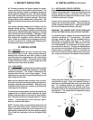
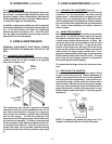
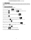
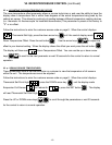
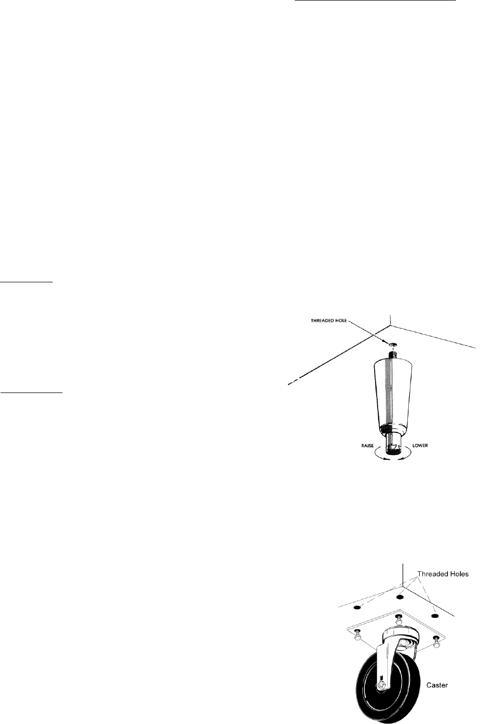
To install the legs or casters, first raise and block the
reach-in a minimum of 7” from the floor. For install-
ing legs, thread the legs into the threaded holes on
the bottom of the cabinet (see figure 1). Be certain
that all legs are tightly secured. When the unit is set
in its final position, it is important for proper opera-
tion that the unit be level. The legs are adjustable for
this purpose, turn the bottom of the leg counterclock-
wise to raise it, clockwise to lower it. Level the unit
from front to back as well as side to side in this man-
ner, using a level placed in the bottom of the cabinet.
Please note that Traulsen units are not designed to be
moved while on legs. If the unit requires moving, a
pallet jack or forklift should be used to prevent dam-
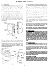
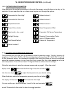
age. For installing casters, the casters are “plate”
type, and require the use of four (4) bolts each to se-
cure them firmly to the cabinet bottom at each corner
(see figure 2). The caster bolts are tightened using a
1/2” socket wrench.
-2-
II. RECEIPT INSPECTION
All Traulsen products are factory tested for perfor-
mance and are free from defects when shipped. The
utmost care has been taken in crating this product to
protect against damage in transit. All interior fittings
have been carefully secured and the legs are boxed
and strapped inside to prevent damage. Door keys
will be attached to the handle with a nylon strip. The
handle is protected by an easily removable nylon net-
ting.
You should carefully inspect your Traulsen unit for
damage during delivery. If damage is detected, you
should save all the crating materials and make note
on the carrier’s Bill Of Lading describing this. A freight
claim should be filed immediately. If damage is sub-
sequently noted during or immediately after installa-
tion, contact the respective carrier and file a freight
claim. Under no condition may a damaged unit be re-
turned to Traulsen & Co. without first obtaining writ-
ten permission (return authorization).
III. a -
LOCATION:
Select a proper location for your Traulsen unit, away
from extreme heat or cold. Allow enough clearance
between the unit and the side wall in order to make
use of the door stay open feature at 120° (self-closing
feature operates up to 90°). The door(s) must be able
to open a minimum of 90° in order to make use of the
maximum clear door width available.
III. b - PACKAGING:
All Traulsen units are shipped from the factory bolted
to a sturdy wooden pallet and packaged in a durable
cardboard container. The carton is attached to the
wooden skid with the use of large staples. These
should first be removed to avoid scratching the unit
when lifting off the crate.
Most exterior stainless steel surfaces have a protec-
tive vinyl covering to prevent scratching during manu-
facturing, shipping and installation. After the unit is
installed in place of service, remove and discard the
covering from all surfaces.
To remove the wooden pallet, first if at all possible, we
suggest that the cabinet remain bolted to the pallet
during all transportation to the point of final installa-
tion. The bolts can then be removed with a 3/4” socket
wrench. Avoid laying the unit on its front, side or
back for removal of the pallet.
NOTE: Traulsen does not recommend laying the unit
down on its front, side or back. However, if you must
please be certain to allow the unit to remain in an up-
right position afterwards for 24 hours before plugging
it in so that the compressor oils and refrigerant may
settle.
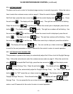
III. INSTALLATION
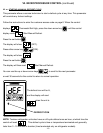
III. INSTALLATION (continued)
Fig. 2
Fig. 1