


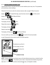
III. d - SHELF PINS:
The unit is supplied with shelves and shelf pins in-
stalled. Check all shelf pins to assure they are tight-
ened down as they may have come loose during ship-
ping. Rotate the pins clockwise until they are secured
against the side of the cabinet.
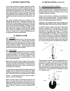
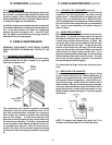
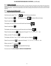
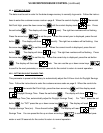
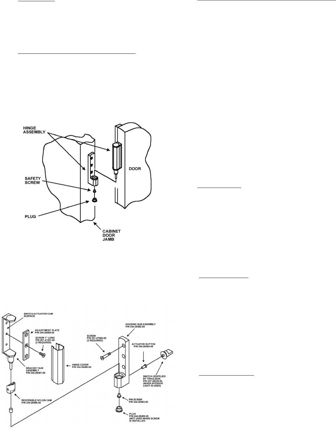
III. e - REMOVING THE DOORS & HARDWARE:
In order to fit through narrow (less than 35”) doorways,
it may be sometimes be necessary to remove the
door(s), and/or hinges. To remove any solid door, be-
gin by removing the plug at the bottom of the top hinge.
Inside the hinge there is a small screw which secures
the door in place. Remove this with a flat head screw-
driver and the door can then be lifted off the hinge
(see figure 3).
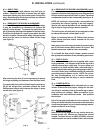
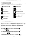
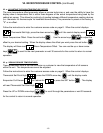
After removing the door, it is now necessary to remove
the hinge assembly and hardware from the door itself.
To remove the door portion of the hinge from the door,
lift off the hinge cover and then remove the three
Phillips head screws which secure the hinge in place
on the door (see figure 4).
-3-
III. INSTALLATION (continued)
III. e - REMOVING THE DOORS & HARDWARE
(cont’d)
:
If it is also necessary to remove the hinge hardware
from the cabinet as well, begin by removing the three
Phillips head screws which hold it in place. Set these
components aside for later reassembly (see figure 4).
NOTE: All solid door units include a microswitch for
controlling the interior lighting in the top hinge(s).
Special care should be taken to not damage the wir-
ing for this during the hinge removal process.
The lock keeper will also need to be removed in order
to reduce theroverall cabinet depth to 32”.
Begin by removing the two (2) Phillips head screws
which secure the lock keeper actuator to the lock
keeper bracket.
Next remove the lock keeper bracket by removing the
two (2) flat head screws which secure it in place. Set
these components aside for later reassembly.
To re-install the door and/or hinges, please reverse
the appropriate sections of the preceding procedure.
III. f - CORD & PLUG:
Most self-contained models are supplied with a cord
& plug attached. It is shipped coiled at the top of the
cabinet, secured by a nylon strip. For your safety and
protection, all units supplied with a cord and plug in-
clude a special three-prong grounding plug on the ser-
vice cord. Select only a dedicated electrical outlet with
grounding plug for power source. NOTE: Do not un-
der any circumstances, cut or remove the round
grounding prong from the plug, or use an extension
cord.
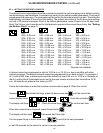
III. g - POWER SUPPLY:
The supply voltage should be checked prior to con-
nection to be certain that proper voltage for the cabi-
net wiring is available (refer to the serial tag to deter-
mine correct unit voltage). Make connections in ac-
cordance with local electrical codes. Use qualified
electricians.
Use of a separate, dedicated circuit is required. Size
wiring to handle indicated load and provide necessary
overcurrent protector in circuit (see amperage require-
ments on the unit’s serial tag).
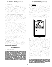
III. h - WIRING DIAGRAM:
Refer to the wiring diagram for any service work per-
formed on the unit. Should you require one, please
contact Traulsen Service at (800) 825-8220, and pro-
vide the model and serial number of the unit involved.
Fig. 3
Fig. 4