


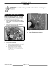
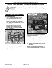
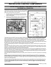
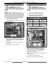
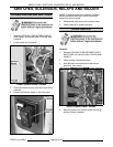
MODEL C24EA - WATER LEVEL CONTROL COMPONENTS
F35453 (July 2008) Page 22 of 68
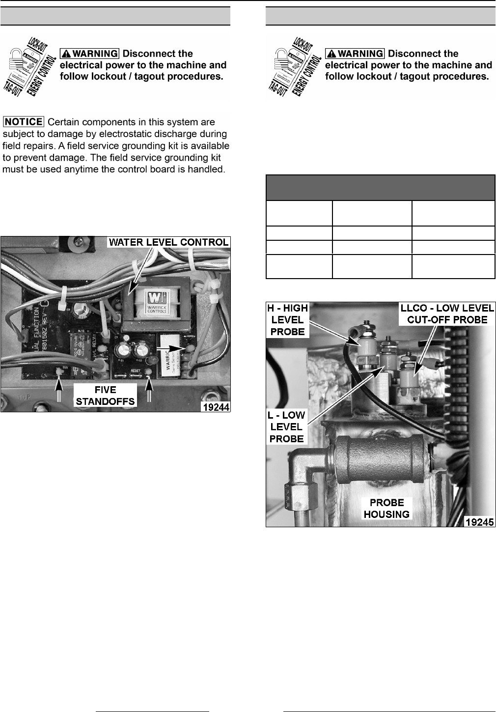
WATER LEVEL CONTROL
1. Remove FRONT BASE PANEL as outlined
under COVERS AND PANELS.
2. Squeeze tab on plastic standoffs (5) to release
water level control.
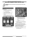
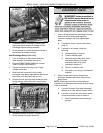
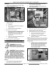
3. Note electrical connections then disconnect
lead wires from water level control (WLC). Refer
to the machine schematic when installing water
level control.
4. Reassemble parts and lead wires removed in
reverse order.
5. Check steamer for proper operation.
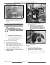
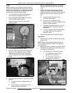
WATER LEVEL PROBES
1. Remove RIGHT SIDE BASE PANEL as
outlined under COVERS AND PANELS.
2. Note locations of electrical wiring and
disconnect lead wires to water level probes.
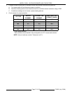
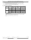
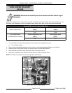
WATER LEVEL PROBE ELECTRICAL
CONNECTIONS
Water Level
Control
Wiring Water Level
Probe
H # 5 A - Blue H - High Level
L # 6 B - Yellow L - Low Level
LLCO # 7 C - Red
LLCO - Low Level
Cut-Off
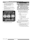
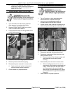
3. Remove probes from probe housing.
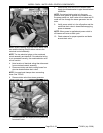
NOTE: Probes should be cleaned thoroughly.
Remove all accumulated deposits from insulator
using a soft cloth. Do not use anything abrasive on
insulators. If probes are dirty, delime steam
generator after assembling.
NOTE: Apply pipe thread sealant to threads of probe
before installation.
4. Reverse procedure to install.
NOTE: Perform steam generator DELIMING.