


MODEL C24EA - ELECTRICAL OPERATION
F35453 (July 2008) Page 52 of 68
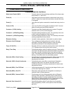
SMART CYCLE POWER
MANAGEMENT
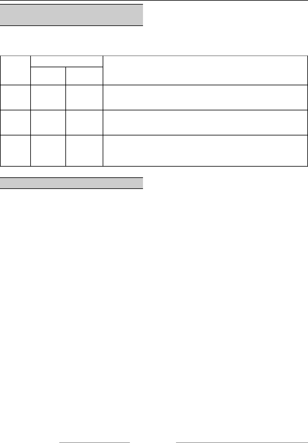
Reduces energy use by not powering all the heating elements in steam generator and heat exchanger when the
steamer is at operating pressure and one cooking compartment in use. When both cooking compartments are in
use, all of the heating elements in the steam generator and heat exchanger are powered.
Steamer
Heating Elements
Description
Steam
Generator
Heat
Exchanger
6 pan 2 2 One cooking compartment in use, only one steam generator heating
element and one heat exchanger element are powered thru limiting
contactor (1CON) and regulating contactor 1 (2CON).
10 pan 3 2 One cooking compartment in use, two steam generator heating elements
and one heat exchanger element are powered thru limiting contactor
(1CON) and regulating contactor 1 (2CON).
6 or
10 pan
As listed
above
As listed
above
Two cooking compartments in use, all steam generator heating elements
and both heat exchanger elements are powered thru limiting contactor
(1CON), regulating contactor 1 (2CON) and regulating contactor 2
(3CON).
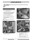
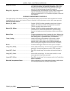
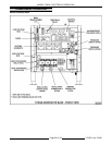
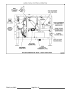
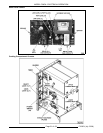
SEQUENCE OF OPERATION
Refer to the following diagrams when reviewing sequence of operation: Steam generator schematic, cooking
compartment schematic and heating element wiring diagrams (for heat exchanger relay contacts K10 and K12).
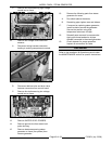
The control board delime time delay relay 2 (TDR) and drain time delay relay (TDR) jumpers are set at their default
times as shown on the schematic.
NOTE: If power switch is off when service voltage is applied, steamer will enter timed drain cycle.
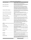
Initial Fill and Pre-Heat
1. Conditions (steamer previously operated and drain cycle timed out).
A. Steamer connected to correct voltage.
1) 120VAC potential across X1 and X2 on secondary side of main transformer.
B. Steamer connected to cold water supply with correct water requirements.
C. LED 1 lit (power to control board).
D. Power switch is off (1S).
1) LED 13 lit. Delime 1 (TDR) on control board timed out. Time delay has no output from load
terminal.
2) Delime 2 (TDR) on control board timed out. Time delay has no output from load terminal.
3) LED 9 lit. Drain (TDR) on control board timed out. Time delay has no output from load terminal.
E. Delime switch (2S) is off (center position).
F. Compartment timers off and doors open.
G. Condensate thermostat thermostat (1TAS) open.
H. Pressure switch (2PAS) closed.
1) LED 12 lit. Vacuum relief solenoid (5SOL) energized. Solenoid valve must be open to provide air
vent to allow steam generator to fill.
I. Steam generator high limit (2TAS) closed.
J. Heat exchanger high limit (3TAS) closed.