


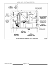
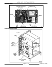

MODEL C24EA - ELECTRICAL OPERATION
F35453 (July 2008) Page 54 of 68
a) Ready lights (1LT) (green) are lit for the upper and lower compartments.
b. K1-5/1 N.C. contacts open.
a) LED 4 off. Regulating contactor 2 (3CON) de-energized.
2) LED 3 off. Regulating contactor 1 (2CON) de-energized.
B. Power removed from heating elements. Steam generator heating stops.
Timers Set (Upper & Lower Compartments)
1. Timers set for timed cooking and doors closed.
A. Upper compartment - Timer contacts 11/13 and 21/23 close.
1) LED 6 lit. Upper cavity relay (K8) energized. K8-3/5 N.O. contacts close.
a. LED 8 lit. Cavity condensate solenoid (2SOL) energized. Compartment drain line condensate
cooled.
b. Heat exchanger relay (K10) energized. K10-3/5 N.O. contacts close and heat exchanger
element (1) begins heating.
c. K8-6/4 N.O. contacts close.
2) Cook light (2LT) (red) lit. Steam solenoid energized (steam enters cooking compartment).
3) Timer motor energized.
B. Lower compartment - Timer contacts 11/13 and 21/23 close.
1) LED 7 lit. Lower cavity relay (K9) energized. K9-3/5 N.O. contacts close.
a. LED 8 lit. With upper compartment timer already set, cavity condensate solenoid (2SOL) and
heat exchanger relay (K10) are energized thru K8-3/5 closed contacts.
a) K10-3/5 contacts close and heat exchanger element (1) begins heating.
b. Heat exchanger relay (K12) energized thru K8-6/4 and K9-3/5 N.O. contacts. Heat exchanger
element (2) begins heating.
c. If lower compartment timer is the only timer set, cavity condensate solenoid (2SOL) and heat
exchanger relay (K10) are energized thru K8-1/5 N.C. contacts. Compartment drain line
condensate is cooled. K10-3/5 contacts close and heat exchanger element (1) is energized.
2) Cook light (2LT) (red) lit. Steam solenoid energized (steam enters cooking compartment).
3) Timer motor energized.
2. Steam generator pressure drops below pressure switch (1PAS) set point.
A. Regulating contactor 1 (2CON) and regulating contactor 2 (3CON) are energized and power the heating
elements until pressure switch is satisfied. The pressure switch will cycle the heating circuit as necessary
to maintain steam generator pressure.
1) LED 3 will cycle on/off with regulating contactor 1 (2CON). LED 4 will cycle on/off with regulating
contactor 2 (3CON).
Water Refill (After Initial Fill)
1. The water refill cycle will occur whenever the water level is below the low level probe and will not affect the
operation of either the preheat or cook cycle.
A. Water level drops below low level (L) probe.
1) Internal latching relay coil (ILR) on WLC de-energized. ILR-1 contacts return to N.O. condition.
2) HL LED lit. High level coil (HL) energized by ILR-2 contacts returning to N.C. condition.
a. WLC (HL) contacts close. Slow fill solenoid (4SOL) energized.
B. Water level reaches high level (H) probe.
1) Internal latching relay coil (ILR) on WLC energized and locked thru the low level probe (L) and ILR-
1 closed contacts.