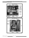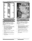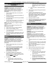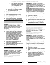
VHX SERIES STEAMERS - COMPONENT FUNCTION
F24700 (October 2001) Page 10 of 68
COMPONENT FUNCTION
CABINET BASE BOILER CONTROLS
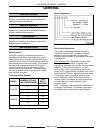
Power Switch (ON/OFF)
......... When turned ON, supplies power to the control circuit.
Reset Switch (Manual)
.......... Resets the low water level safety circuit on initial startup or the
occurrence of a low water condition and allows the boiler to fill with
water. Also, resets the high pressure level safety circuit on initial startup
or the occurrence of a high pressure condition and allows the gas
ignition cycle to start.
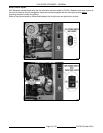
Boiler Fill Solenoid Valve
........ Admits water to the boiler when demanded by the water level control to
maintain the correct water level in the boiler.
Cold Water Condenser
Solenoid Valve
................. Allows cold water flow into the boiler blowdown drain box to condense
steam and cool the hot water before its discharge into the drain.
Blowdown/Drain
Solenoid Valve
................. A normally open valve (N.O.) that closes to allow boiler to fill and
pressurize when power switch is turned ON and opens when power
switch is turned off to blowdown and drain the boiler. This valve is
plumbed into the drain line of the boiler.
Cycling Pressure Switch
......... Controls boiler pressure between prescribed limits by turning the heat
source on and off.
High Limit Pressure Switch
...... Protects the boiler from pressures above 15 psi by removing power from
the heating circuit. This pressure setting is higher than the cycling
pressure switch in order to turn off the heat source before the boiler
pressure reaches its limit. After the pressure drops below approximately
12psi, press the rest switch of the front control panel to rest the safety
circuit.
Main Water Level Control
........ A dual functioning control that allows water to fill and maintain the
proper level in the boiler providing differential water level control; and
shuts off the main gas valve if the water level drops too low providing
low level cut-off protection. The water level control works by using three
different probe lengths to monitor the water level. The probes consist of
a high level (HL), low level (LL) and low water cut-off (LLCO).
Auxiliary Water Level Control
..... A back up to the low level cut-off on the main control. Protects the boiler
and heating system components from a low water cut-off condition by
opening the 24VAC voltage path to the heating system circuit. Also,
energizes the low water "light" on the front control panel.
Transformer
................... Provides 24VAC power to ignition control module and heating circuit.
Ignition Control Module
......... Controls and monitors gas heating. Energizes pilot valve coil to supply
gas to pilot, generates spark to ignite gas at the pilot, monitors the
presence of flame and energizes the main and pilot valve coils on the
main gas valve upon a call for heat.
Main Gas Valve
................ A gas solenoid valve that opens to allow gas flow to the main burner
after the successful ignition of the pilot burner when a call for heat is
made.
Pilot Gas Valve
................ A gas solenoid valve that opens to allow gas flow to the pilot to ignite the
main burner when a call for heat is made. The valve is energized by a
time delay circuit on the relay board during ignition trial for
approximately 15 seconds. New style controls only.
Combustion Blower
............ Provides forced air to the gas/air mixture for gas pilot and main burner
combustion.


