


VHX SERIES STEAMER - ELECTRICAL OPERATION
F24700 (October 2001)Page 41 of 68
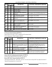
ELECTRICAL OPERATION
WATER LEVEL CONTROLS
Low Level Cut-Off & Differential Control
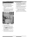
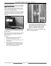
The steamer is equipped with three water level
sensing probes (high, low and low level cut-off) and
a single water level control board (solid state). The
water level control board performs two functions: 1)
Provide low level cut-off protection to shut off the
heat source in case the water level drops below the
low level cut-off (LLCO) probe. 2) Perform as a
differential level control to maintain the water level
between the low and high water level probes.
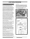
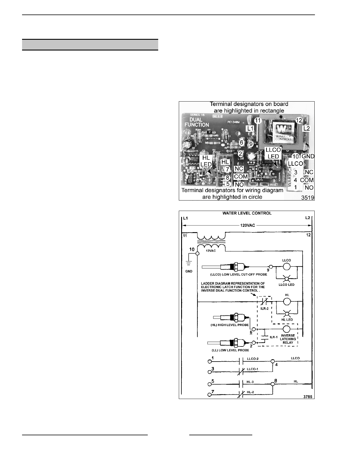
The water level control (WLC) has input voltage
(120VAC) across terminals 11 and 12 which powers
the primary side of the transformer. On one side of
the transformer secondary, power is provided to the
control by a series path through chassis ground
(terminal 10). The other side of the transformer
secondary (12VAC) is attached to the probe that
directs power to the other side of board relay coils
(LLCO and HL) and to the Inverse Latching Relay
(ILR) electronic circuit on the board. As water enters
the boiler, it becomes part of the water level
control’s circuit. When the water level in the boiler
reaches a probe, that circuit is completed.
The inverse latching relay of the board is de-
energized, leaving the ILR-1 (N.O.) and ILR-2 (N.C.)
contacts in their shelf state.
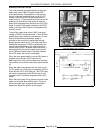
When the main power switch is turned ON, power is
supplied to the WLC board which energizes the high
level (HL) relay, closes HL-3 normally open
contacts, and illuminates the HL relay LED. With the
HL-3 contacts closed, the boiler fill solenoid is
energized and water begins filling the boiler.
When the water level reaches the low level cut-off
(LLCO) probe, the LLCO relay is energized and
illuminates the LLCO LED. With the LLCO-2
contacts closed the heat source is then energized.
The LLCO relay will remain energized and its LED
will stay lit until the water level in the boiler drops
below the LLCO probe.
NOTE:
Auxiliary control(s)
in the heating circuit must also be satisfied before
heating can start.
When the water level reaches the low level (LL)
probe, power to terminal 2 on the WLC board is
present but no switching occurs.
After the water level reaches the high level (HL)
probe, the inverse latching relay of the board is
energized and locked through the low level probe
(LL) and ILR-1 contacts. With ILR-2 contacts open,
this de-energizes the HL relay and the HL LED goes
out. With the HL-3 contacts open, the boiler fill
solenoid is de-energized, stopping the flow of water
into the boiler.
When the water level drops below the low level (LL)
probe, power is removed from the inverse latching
relay, the HL relay energizes through ILR-2 and HL
contacts change state. The fill solenoid is energized
through HL-3 to refill the boiler and the HL LED is lit.
The HL relay and LED will toggle ON and OFF
during a cooking cycle as needed.