


VHX SERIES STEAMER - SERVICE PROCEDURES AND ADJUSTMENTS
F24700 (October 2001)Page 31 of 68
a. If ignitor sparks and pilot lights,
proceed to step 7.
b. If ignitor does not spark, proceed
to step "5)" below.
5) Restart power ON sequence by
"rapidly" turning the power switch
OFF then back ON. A rapid switching
is needed to keep the boiler from
starting automatic blowdown.
a. Grasp the ignitor terminal and
rotate the ignitor approximately
45°.
b. Re-connect ignition cable.
6) Press the reset switch to start the
ignition process.
a. If ignitor sparks and pilot lights,
proceed to step 7.
b. If ignitor does not spark, repeat
steps "5)" through this step until
rod has been rotated 360°.
7. Verify main burner ignition.
A. If main burner lights and remains lit with
no intermittent problems, then burner is
functioning properly.
B. If main burner does not
light or shows
intermittent problems, then check the main
burner pressure setting as outlined under
"GAS MANIFOLD PRESSURE
ADJUSTMENT".
1) If pressure is ok but intermittent
burner problems continue, then the
following components must be
examined.
2) Turn the power switch OFF and allow
the boiler to blowdown.
WARNING:
DISCONNECT THE ELECTRICAL
POWER TO THE MACHINE AT THE MAIN
CIRCUIT BOX. PLACE A TAG ON THE CIRCUIT
BOX INDICATING THE CIRCUIT IS BEING
SERVICED.
WARNING:
SHUT OFF THE GAS BEFORE
SERVICING THE UNIT.
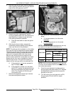
3) Remove burner head assembly as
outlined under "BURNER HEAD
ASSEMBLY" in "REMOVAL AND
REPLACEMENT OF PARTS".
4) The complete or intermittent loss of
burner ignition or a burner operation
that is loud and noisy may indicate
the burner tube insulation or heat
exchanger casting is damaged.
Verify the burner tube insulation and
heat exchanger casting are intact.
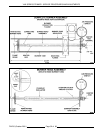
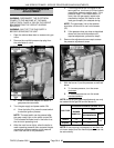
NOTE:
The suggested method for
inspection is to mount a small mirror
to a 2 foot long rod and insert the
mirror inside the burner tube and use
a flashlight to illuminate the area.
NOTE:
If necessary, the complete
burner tube assembly can be
removed to aid in performing the
measurement and inspections.
a. Inspect the ceramic insulation for
damage at the area around the
burner head inside the burner
tube.
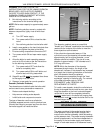
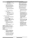
b. Measure ceramic insulation
insertion depth/location from the
end of the insulation that
surrounds the burner head to the
opposite end of the burner tube
(end plate mounting flange). The
dimension should measure
approximately 23 5/8 inches
±1/8. See diagram 5898
"COMPLETE BURNER
ASSEMBLY" at the end of this
procedure.
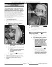
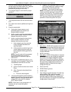
c. Verify that casting debris is not
clogging the "heat transfer fins"
at the end of heat exchanger
casting and that the fins have
not eroded away.
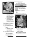
d. Inspect the interior of heat
exchanger casting for signs of
water leakage. Also, signs of
water leakage into the heat
exchanger casting may be
determined by examining the
bottom area of the flue transition
piece and floor.