


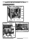
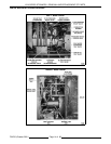

VHX SERIES STEAMERS - COMPONENT FUNCTION
F24700 (October 2001)Page 11 of 68
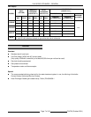
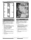
Relay Board
................... Provides a centralized location for wire harness connections and power
transfer through board relays (K1-K7) to the steamer controls. Also,
provides a condition or component troubleshooting indicator by utilizing
seventeen LED’S on the board to represent the status of the condition or
component in the operation sequence. For an LED legend, see "RELAY
BOARD" under "ELECTRICAL OPERATION". New style controls only.
NOTE
: The relay’s below are mounted on the relay board and are not
individually replaceable.
K1 Relay
...................... Energized when Aux LLCO is satisfied and turns ready light (green) ON
if high limit pressure switch is closed. Also, K1 allows K3 to be energized
when the reset switch is pressed.
K2 Relay
...................... Energized when high limit pressure switch is closed (high limit pressure
condition satisfied). When K1 & K2 are energized, the ready light (green)
will be ON.
K3 Relay
...................... When Aux LLCO is satisfied and the manual reset switch is activated,
K3 is energized. When K3 is energized, turns water error light OFF and
allows the ignition sequence to begin. K3 must be energized for ignition
sequence to begin.
K4 Relay
...................... Energized when K2 contacts are closed and manual reset switch is
activated. When K4 is energized, the high pressure light is OFF. When
K3 and K4 are both energized, power to the ignition system is supplied.
K5 Relay
...................... Energized when operating conditions are met and reset switch is
activated. Provides power to start combustion blower.
K6 Relay
...................... Energized by time delay circuit for approximately 15 seconds. When K6
and K7 are energized, power is supplied to the pilot gas valve.
K7 Relay
...................... Energized when pilot voltage (PV) from the ignition module is present.
Also used in the time delay circuit.
Pilot
......................... Ignites to light the main burner upon a call for heat.
Main Burner
................... Heats the water in the boiler to generate steam.
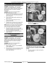
Water Level
Gauge Assembly
............... Permits a visual confirmation the water level is being maintained in
boiler during operation. The correct water level is approximately one
visible inch in the glass. The manual valves at the top and bottom of this
assembly must be fully open and only closed if the glass tube is
damaged.
Water Inlet Valve (manual)
....... The water inlet valve is used to stop water flow to the steamer when the
steamer is being serviced. This valve should remain open during normal
operation.
Inline Water Strainer
............ A "Y" strainer is installed upstream of the blowdown solenoid valve to
prevent foreign matter from becoming lodged in the valve. A strainer
(not supplied) should also be installed in the water supply line to prevent
foreign matter from becoming lodged in the fill or cold water condenser
solenoid valves and to keep unwanted particles out of the system.
Pressure Relief Valve
........... A mechanical device that opens to relieve steam pressure in the boiler if
the pressure exceeds 13 psi.
High Pressure Relief Valve
....... A back-up mechanical device that opens to relieve steam pressure in
the boiler if the pressure exceeds 15 psi.
Descaler
...................... Hangs below the water level inside the boiler and is used to help control
boiler surface scaling. Two descalers are used in each boiler.
Boiler Pressure Gauge
.......... Indicates the amount of steam pressure in the boiler.
Steam Header Assembly
......... Main steam supply line from the boiler to the steam header inlet in the
cooking control compartment.