


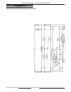
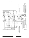
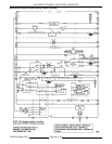

VHX SERIES STEAMER - ELECTRICAL OPERATION
F24700 (October 2001)Page 47 of 68
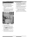
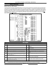
NOTE:
Relay K4 remains energized through
K4(1) N.O. locking circuit.
1)
N8 goes out.
K4(1) N.O. contacts
close and K4(1) N.C. contacts open.
2) High pressure light (control panel)
goes out.
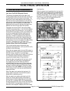
C.
N11 lit.
K4(2) N.O. contacts close.
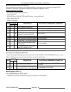
1) K5 is energized (24VAC).
a.
N12 lit.
K5(1) N.O. contacts
close.
a) Combustion blower starts.
7.
N13 lit.
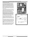
When the combustion blower
generates sufficient air pressure, the air
pressure switch N.O. contacts close.
A. Ignition module is powered (24VAC).
1) Ignition module starts sparking.
2)
N14 lit.
Pilot voltage (PV) N.O.
contacts close.
a. K7 is energized.
a) K7(1) N.O. contacts close.
3) 15 sec. timer circuit (board level,
solid state timer) energized and
timing of pilot gas valve ON time
begins.
a. K6 energized.
a)
N15 lit.
K6(1) N.O. close.
4) Pilot gas valve energized, pilot valve
opens for gas to flow.
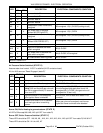
B. Pilot flame established. Micro amp flame
"sense" current rectified to ignition module
through ignition cable.
1) Sparking stops.
2)
N16 lit.
Main voltage (MV) N.O.
contacts close.
a.
N17 LED lit.
Proves LLCO on
water level board closed.
b. Main gas valve opens, burner
lights and boiler begins to heat
up.
C. 15 seconds after ignition module
energized, relay board timer circuit times
out.
1)
N15 goes out.
K6 de-energized.
a. Pilot valve closes, gas flow stops
to pilot.
NOTE:
If pilot ignition is not established within
the allotted 15 seconds, the ignition module
continues to spark. To attempt to relight the
pilot, quickly cycle the reset switch to prevent
the boiler from draining. If the pilot is not
established within 90 seconds from the ignitor
module being energized, the ignition module
locks out power to the gas valves. The module
remains locked out until the power switch is
turned to OFF then ON and the manual reset
switch is pressed to r e-start the ignition trial
cycle.
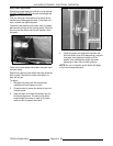
D. As boiler heats up and builds pressure,
some by-pass water/steam is produced
which runs into the steam drain box. This
causes the cold water condenser (CWC)
solenoid to cycle, cooling the drain water
and condensing any steam vapors before
exiting the drain. The CWC solenoid is
powered through the CWC cycling
thermostat.
NOTE:
On initial cold startup only, the boiler
pressure may overshoot and cause the
mechanical pressure relief valve to open
momentarily.
E. As long as the ignition control module
senses a burner flame, the internal main
voltage (MV) contacts (N.O.) on the
ignition module remain closed, and main
gas valve stays ON.
NOTE:
PV N.O. contacts are also closed, but
K6 contacts are open to keep pilot valve
closed.
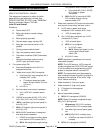
8. Boiler steam pressure reaches upper limit set
point of 10 PSI (Approx. 15 minutes).
A. Cycling pressure switch open.
1)
N9, N10, N11, N12, N13 go out.
a. K5 de-energized.
a) K5(1) N.O. contacts open.
b. Combustion blower is de-
energized.
a) Air pressure switch opens.
B. Ignition module is de-energized
1) PV and MV contacts open.
a.
N14, N16, N17 go out.
b. Main gas valve closes, burner
goes out.
c. K7 de-energized.
a) K7(1) open
9. Boiler steam pressure drops below lower limit
set point of 8 PSI and the cycling pressure
switch close.
A. Boiler steam pressure is maintained by the
cycling of the pressure switch between the