


VHX SERIES STEAMER - ELECTRICAL OPERATION
F24700 (October 2001) Page 48 of 68
upper and lower set point limits. The
cycling pressure switch continues to
energize and de-energize the heating
circuit to cycle the burner ON and OFF.
This sequence continues until one of the
following occurs:
1) Power switch is turned OFF.
2) Boiler water level drops below the
LLCO probes for the main water level
control (WLC) and the auxiliary low
level control.
3) Boiler pressurizes to 15 PSI, causing
the high limit pressure switch to open.
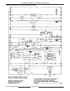
Water Refill (After Initial Fill)
1. Water level drops below low level probe (LL).
A. HL relay is energized.
1) HL-3 (N.O.) contacts close.
2) Fill solenoid is energized.
3) HL LED comes ON.
2. Water reaches LL (low level) probe.
3. Water reaches high level probe.
A. HL relay is de-energized.
1) HL-3 (N.O.) contacts open.
2) Fill solenoid is de-energized.
3) HL LED goes out.
4. The water refill cycle will occur whenever the
water level is below the low level probe and will
not affect the operation of either the preheat or
cook cycle.
Boiler Blowdown/drain
1. Power switch turned OFF.
A. Automatic blowdown solenoid valve (N.O.)
is de-energized and valve opens to drain
the boiler.
B. Power is removed from all components
except cold water condenser (CWC)
thermostat and solenoid valve. The CWC
thermostat cycles as necessary to lower
the discharge temperature of the water
and condense steam going into the drain.
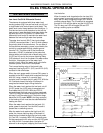
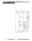
OLD STYLE CONTROLS - BOILER
This sequence of operation is written for boiler
bases with the old style boiler controls. See
"BOILER CONTROL STYLES" under "GENERAL".
Refer to schematic diagram 5480.
Initial Fill And Preheat
1. Conditions.
A. Power switch OFF.
B. Boiler connected to correct voltage
(120VAC).
1) Power to cooking compartment
controls. See "COOKING
COMPARTMENT CONTROLS" later
in this section.
C. Boiler properly grounded (boiler and water
level controls share a common ground)
D. Gas and water supply valve(s) ON.
E. Main gas valve ON.
F. Cycling pressure switch CLOSED.
G. High limit pressure switch CLOSED.
H. Cold water condenser (CWC) thermostat
OPEN.
I. Automatic blowdown valve (A.B.D.) OPEN
and boiler empty.
2. Turn power switch ON.
A. Relay R4 energized and R4 contacts
(N.O.) CLOSE.
B. Power ON light (red) comes ON.
C. Blowdown solenoid valve is energized and
CLOSES.
D. Auxiliary water level control is powered.
1) Aux. LLCO N.O. contacts remain
OPEN (Aux. LLCO relay de-
energized).
E. Low water level light (amber) comes ON.
NOTE:
The low water indicator light will remain
ON and the safety circuit de-energized until the
water level in the boiler reaches the auxiliary
low level cut-off probes (aux. LLCO, minimum
level) for the aux. water level control, and the
manual reset switch is pressed.
F. High pressure light (amber) comes ON.
NOTE:
The high pressure indicator light will
remain ON and the safety circuit de-energized
until the manual reset button is pressed (high
limit pressure switch must be closed).
G. Power is connected through the high limit
pressure switch contacts (N.C.) to one side
of the push button reset switch.
H. Water level control is powered (Low Level
Cut-off & Differential Control).
1) High level (HL) relay is energized, HL
contacts (N.O.) CLOSE
a. HL LED lights up.
b. Fill solenoid is energized and
water begins filling boiler (fill
time 4-11 min.).