


VHX SERIES STEAMER - SERVICE PROCEDURES AND ADJUSTMENTS
F24700 (October 2001) Page 38 of 68
Spark Verification Test
1. Turn the power switch OFF.
2. Check to ensure that all electrical terminal
connections on the ignition control module and
the ignitor rod are clean and tight. If the ignition
cable appears to be damaged, replace it and
re-try lighting burner.
3. Verify that the ignition control module and the
burner ground have a good ground connection.
A. If loose connections are found, make the
necessary adjustments and check for
proper operation.
B. If connections are ok but sparking does
not occur, proceed to step 4.
4. Remove ignition cable boot from the ignitor rod
terminal and check ignitor position in the burner
head assembly.
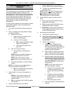
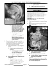
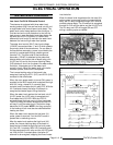
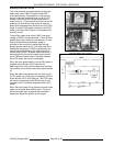
A. Measure distance ignitor terminal extends
past ignitor nut, approximately 3/4" to 7/8".
See diagram 5898 "COMPLETE BURNER
ASSEMBLY" under "MAIN BURNER
IGNITION CHECKS”.
NOTE:
Touch ignitor terminal only and not
the ceramic insulator.
1) If distance is ok, proceed to step 5
and perform steps B thru E.
2) If distance is other than stated, loosen
ignitor nut, set the ignitor position.
3) Re-connect ignition cable.
B. Turn the power switch ON and allow the
boiler to fill.
C. Press reset switch to start the ignition
process.
1) If pilot lights, then ignition system is
working properly.
2) If ignitor does not spark, proceed to
step 5.
5. Turn the power switch OFF.
A. Remove ignition cable boot from the
ignitor rod terminal.
B. Grasp the ignitor terminal and rotate the
ignitor approximately 45°.
NOTE:
Touch ignitor terminal only and not the
ceramic insulator.
C. Re-connect ignition cable.
D. Turn the power switch ON and allow the
boiler to fill.
E. Press reset switch to start the ignition
process.
1) If pilot lights, then ignition system is
working properly.
2) If ignitor does not spark, repeat steps
E thru this step until rod has been
rotated 360°.
3) If ignitor still does not spark, proceed
to step 6.
WARNING:
SHUT OFF THE GAS BEFORE
SERVICING THE UNIT.
6. Turn the power switch OFF.
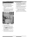
7. Remove the burner head assembly as outlined
under "BURNER HEAD ASSEMBLY" in
"REMOVAL AND REPLACEMENT OF PARTS"
and check the following:
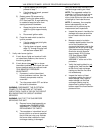
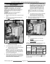
A. The gap between the spark probe and the
ground pin should be approximately 0.090"
to 0.100". Adjust as necessary. See
diagram 5899 "BURNER HEAD
ASSEMBLY" under "MAIN BURNER
IGNITION CHECKS".
B. Inspect the ceramic flame rod insulator for
cracks or evidence of exposure to extreme
heat, which can permit leakage to ground.
If either of these conditions exist, then
replace ignitor rod and re-test.
1) If replacing ignitor rod, loosen the
ignitor rod mounting nut and remove
the ignitor rod from the burner head
assembly.
WARNING:
THE FOLLOWING STEPS REQUIRE
POWER TO BE APPLIED TO THE UNIT DURING
THE TEST. USE EXTREME CAUTION AT ALL
TIMES.
8. Verify spark at electrode.
A. Place the assembly on the floor and attach
a temporary ground wire from the burner
ground on the heat exchanger to the
burner head assembly.
B. Turn the power switch ON and press the
reset switch.
C. Observe spark condition from ignitor.
1) If a good spark from ignitor is present
then the ignition system is working
properly.
2) If ignitor is still not sparking, replace
the ignition control module and repeat
steps 8A and 8B to check for proper
operation.
3) After making the necessary
component adjustments or
replacements, re-assemble and
check for proper operation.