


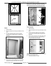

VHX SERIES STEAMER - SERVICE PROCEDURES AND ADJUSTMENTS
F24700 (October 2001) Page 30 of 68
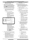
MAIN BURNER IGNITION
CHECKS
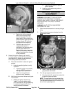
The complete gas burner assembly is located inside
the heat exchanger casting in the boiler. The
perforated burner head functions as both pilot and
main gas burner. The inner portion of the perforated
burner head serves as the pilot to light the main
burner during the trial for ignition. Once the main
burner lights, the flame encompasses the entire
perforated burner head and the pilot flame
extinguishes.
If burner ignition problems are encountered, perform
the following checks to ensure components are
adjusted properly.
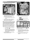
1. Turn power switch ON and allow the boiler to
fill.
2. Verify "low water" and "high pressure" safety
circuits are satisfied.
A. Water Level in boiler.
1) Approximately one visible inch of
water in the sight glass.
2) Auxiliary LLCO is satisfied.
a.
N2
on relay board ON (low water
safety circuit satisfied).
b. LED on auxiliary water level
board ON.
B. High Limit Pressure Switch
1) Zero reading on boiler pressure
gauge.
NOTE:
Burner cycles ON at less than or
equal to 8 PSI and OFF at 10 PSI.
NOTE:
High Limit Pressure Switch
automatically resets at approximately 12
PSI.
C. Press the reset switch to reset the safety
circuits.
NOTE:
Hi Pressure and low water lights on
front control panel should be OFF.
1)
N3
on relay board ON (high pressure
safety circuit satisfied).
3. Verify blower is running and its operation is
quiet.
NOTE:
A "noisy" blower rotation may
indicate bearing wear and reduce air
pressure output.
A.
N12
on relay board ON (120VAC supplied
to the blower).
4. Verify air pressure switch is CLOSED.
A.
N13
on relay board ON (air pressure
switch CLOSED and condition satisfied).
B. Pilot gas valve energized and ignition
sequence starts.
NOTE:
If N13 is not
ON or Pilot gas valve is
not
energized, then check the air pressure
switch setting as outlined under "AIR
PRESSURE SWITCH ADJUSTMENT".
5. Verify 24VAC to ignition module and pilot
valve.
A.
N1
on relay board ON (24VAC is being
supplied for the system).
B.
N13
on relay board ON (24VAC is being
supplied to the ignition module).
C.
N14 & N15
on relay board ON (24VAC is
being supplied to the pilot ignition timing
circuit and the pilot valve.
6. Verify spark and pilot ignition.
A. If pilot lights, proceed to step 7.
B. If sparking occurs but pilot does not
light,
then check the pilot pressure setting as
outlined under "GAS PILOT PRESSURE
ADJUSTMENT".
C. If spark is not
occurring:
1) Restart power ON sequence by
"rapidly" turning the power switch
OFF then back ON. A rapid switching
is needed to keep the boiler from
starting automatic blowdown.
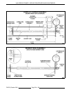
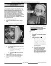
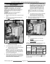
2) Remove ignition cable boot from the
ignitor rod terminal and check ignitor
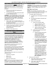
position in the burner head assembly.
3) Measure distance the ignitor terminal
extends past the ignitor nut. Distance
should measure approximately 3/4" to
7/8". See diagram 5898 "COMPLETE
BURNER ASSEMBLY" at the end of
this procedure.
NOTE:
Touch ignitor terminal only
and not the ceramic insulator.
a. If distance is ok, proceed to step
5) below and perform step "a"
and "b" then continue with step
"6)".
b. If distance is other than stated,
loosen ignitor nut, set the ignitor
position and then re-tighten the
ignitor nut.
c. Re-connect ignition cable.
4) Press reset switch to start the ignition
process.