


- 8 -
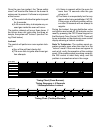
L1
N
BK
BK
R
W
IGNITION
SWITCH
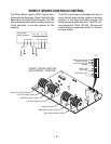
DIRECT SPARK
IGNITION CONTROL
643217910
TOP BURNERS GND
10-PIN CONNECTOR
J1
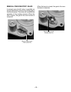
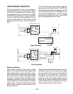
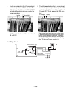
This 120 VAC is detected by the control, and
generates two sparks-per-second to all of the
top burners. Note that in the strip circuit be-
low, 120 VAC is present at the control at all
times through input pin J1-10, and output pin
J1-4.
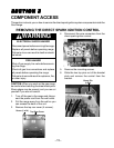
120 VAC is required to:
a)Monitor the internal self-diagnostics of
the control board.
b)Monitor the flame safety circuits to both
of the oven burners.
NOTE: The top burners are operator-moni-
tored, and do not require electronic monitor-
ing.
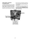
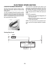
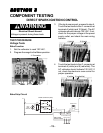
COOKTOP BURNER OPERATION
The top burner spark ignition system is initi-
ated when the burner control is turned to the
LITE position.
120 VAC is supplied through the ignition switch
from the L1 side of the circuit to the direct spark
ignition control at input J1-9 on the control. The
circuit is completed through output pin J1-4 to
the neutral side of the circuit.
ELECTRONIC SPARK IGNITION
Cooktop Strip Circuit