


13
CAUTION
To prevent improper and dangerous op-
eration due to wiring errors, label all wires
prior to disconnection when servicing
controls. Verify proper operation after
servicing.
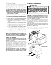
Vll. Circulating Air and Filters
Airflow Conversion
Units can easily be converted from horizontal to vertical
airflow delivery.
Units will ship from the factory ready for horizontal air-
flow. If conversion to vertical airflow is necessary, pro-
ceed as follows:
IMPORTANT: Be sure to save the flue hood assembly
(cardboard box) which is shipped in the return air com-
partment of the unit.
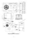
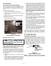
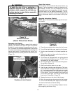
• Remove panels from the bottom of the unit, saving
the mounting screws.
• Remove insulation from outside of supply duct cover.
No insulation should face outside.
• Relocate the panels on to the side of the unit, se-
curing with the screws removed earlier.
• The unit will deliver the same amount of air whether
the airflow is vertical or horizontal. For details, see
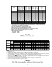
the fan tables on Pages 2 - 5.
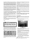
Figure 7
Airflow Conversion
Ductwork
CAUTION
To avoid possible fire, the cardboard
shipping support (located behind the
supply panel) must be removed before
operation.
IMPORTANT: Be sure to save the flue hood assembly
which is shipped in a cardboard box in the return air
compartment of the unit.
Please refer to the unit wiring diagram for electrical con-
nections. When installed, the unit must be electrically
grounded in accordance with local codes or in the ab-
sence of local codes with the latest edition of National
Electrical Code, ANSI/NFPA No. 70.
WARNING
To avoid death or personal injury due to
electrical shock, wiring to the unit must
be properly grounded.
CAUTION
To avoid personal injury or property dam-
age due to fire, use only copper conduc-
tors.
The best protection for the wiring is the smallest fuse or
breaker which will hold the equipment on the line during
normal operation without nuisance trips. Such a device
will provide maximum circuit protection. DO NOT EX-
CEED THE MAXIMUM OVERCURRENT DEVICE SIZE
SHOWN ON UNIT DATA PLATE.
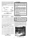
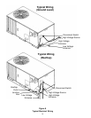
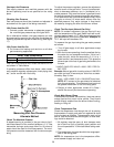
Be sure line voltage connections are made through
weatherproof fittings. All exterior power supply and
ground wiring must be in approved weatherproof con-
duit. Low voltage wiring from the unit control panel to
the thermostat requires coded cable. For ground level
and rooftop wiring refer to Figure 8.
Unit Voltage
The unit transformer is factory connected for 230V op-
eration. If the unit is to operate on 208V, reconnect the
transformer primary lead and induced draft blower mo-
tor leads as shown on the unit wiring diagram.
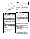
Heat Anticipator Setting
The heat anticipator in the room thermostat must be
correctly adjusted to obtain the proper number of heat-
ing cycles per hour and to prevent the room tempera-
ture from overshooting the room thermostat setting. Heat
anticipator must be set at 0.8 amps.
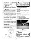
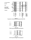
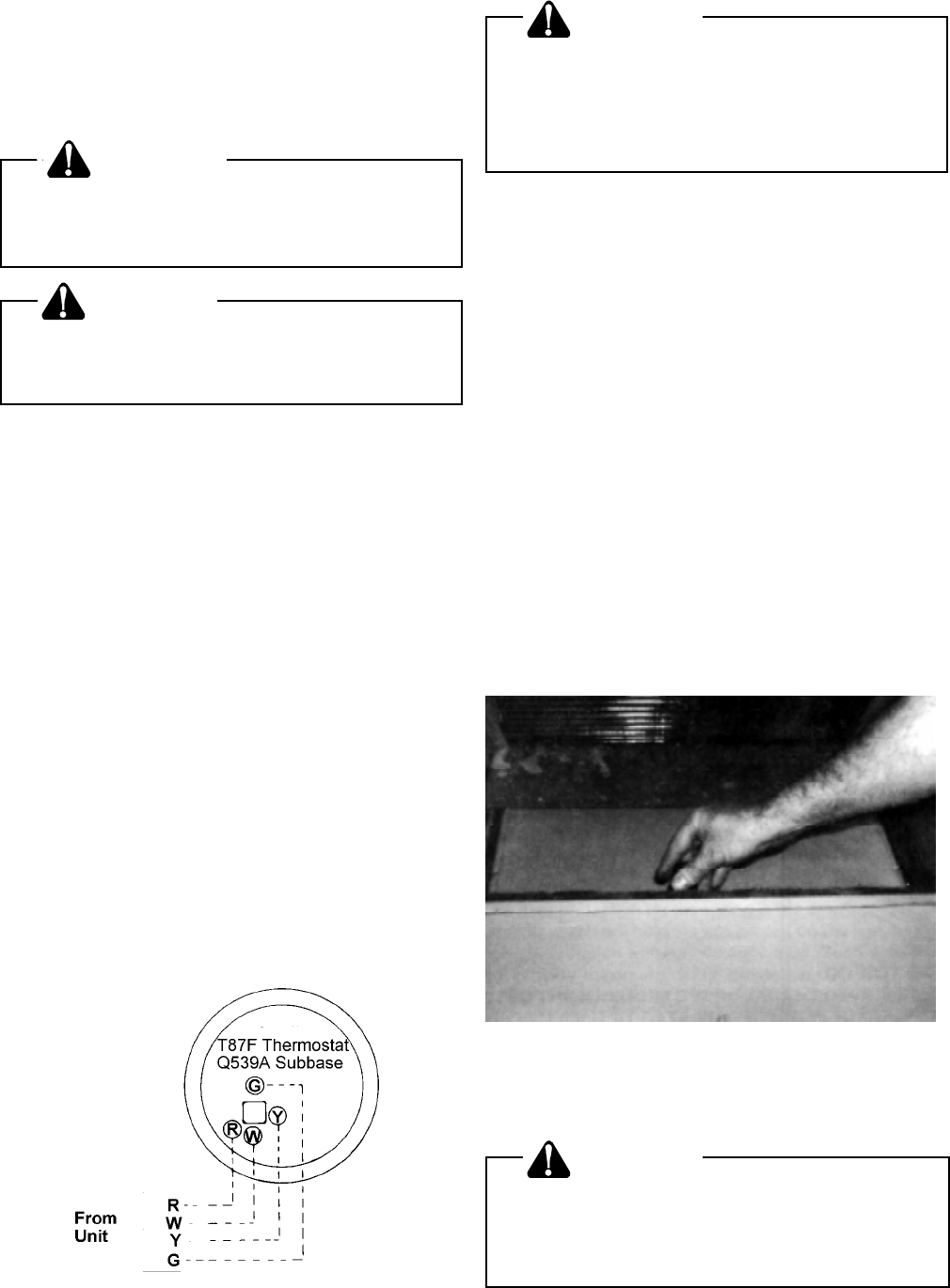
Figure 6
Typical Thermostat and Unit 24 V Wiring
Hookup