


18
X. Heating Sequence of Operations
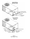
PGB & PGC)
Normal Sequence of Operation - Heating
See Figure 12
1. Thermostat calls for heat. The combustion blower is
immediately energized.
2. The pressure switch contacts transfer.
3. The ignitor is energized and allowed to preheat for
38 seconds.
4. The gas valve is energized delivering gas to the
burners and starting combustion.
5. The control checks the signal from the flame sen-
sor. Gas flow will continue only if a proper signal is
present within seven seconds after the gas valve
opens. As soon as flame is proven, the ignitor is de-
energized.
6. The unit will continue to fire while the helical fan
control heats up. The fan control will start the main
circulating air blower approximately 75 seconds af-
ter the gas valve opens (this time may vary depend-
ing on the control setting).
7. The furnace will deliver heat to the conditioned space
until the thermostat is satisfied.
8. The gas valve and combustion blower will be de-
energized when the thermostat opens.
9. There is a 90 second delay (approximate) before
the main air blower stops. This allows any additional
heat in the heat exchanger to be transferred to the
conditioned space.
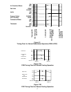
XI. Cooling Sequence of Operations
PGB Normal Sequence of Operations - Cooling
See Figure 13A
1. Thermostat calls for cooling. The compressor and
outdoor fan are energized.
2. Approximately 15 seconds later, the fan time delay
relay closes. The indoor fan now begins operation.
3. The unit will deliver cooling to the conditioned space
until the thermostat is satisfied.
4. The compressor and outdoor fan will be de-ener-
gized when the thermostat opens. It is normal for
the scroll compressor to produce a short burping
sound at this time as its internal pressures are equal-
ized.
5. Refrigerant will continue to flow through the capil-
lary tube (sizes 24 to 42) until the high and low side
pressures are approximately equal. Refrigerant will
continue to flow through the thermal expansion valve
until the high and low side pressures are approxi-
mately 50 PSI apart.
6. The indoor fan continues to run for approximately
45 seconds after the thermostat is satisfied. This
allows additional cooling from the indoor coil to be
transferred to the conditioned space.
PGC Normal Sequence of Operations - Cooling
See Figure 13B
1. Thermostat calls for cooling. The compressor, in-
door fan, and outdoor fan are energized.
2. Approximately 30 seconds later, the indoor fan
ramps up to full speed.
3. The unit will deliver cooling to the conditioned space
until the thermostat is satisfied.
4. The compressor and outdoor fan will be de-ener-
gized when the thermostat opens. It is normal for
the scroll compressor to produce a short burping
sound at this time as its internal pressures are equal-
ized. (The PGC48 has a piston compressor. All other
PGC and PGB have scroll compressors.)
5. Refrigerant will continue to flow through the capil-
lary tube (sizes 24 to 42) until the high and low side
pressures are approximately equal. For the PGC48,
60 and PGB58 refrigerant will continue to flow
through the thermal expansion valve until the high
and low side pressures are approximately 50 PSI
apart.
6. The indoor fan continues to run for approximately
30 seconds after the thermostat is satisfied. This
allows additional cooling from the indoor coil to be
transferred to the conditioned space. Then, the in-
door fan ramps down in 30 seconds to the OFF con-
dition.
XIl. Startup and Adjustment
Heating Startup
General Information
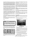
This furnace is equipped with an electronic ignition de-
vice which lights the burners. It also has a power vent
blower to exhaust combustion products.
On new installations, or if a major part such as the gas
valve, pressure switch or fan/limit control has been re-
placed, the operation of the furnace must be checked.
Check furnace operation as outlined in the following in-
structions. If any sparking, odors, or unusual noises are
encountered, shut off electrical power and recheck for
wiring errors, or obstructions in or near the blower mo-
tors. Various shipping materials must be removed be-
fore the indoor and outdoor fans can be operated.
Heat Anticipator Setting
The heat anticipator in the room thermostat must be
correctly adjusted to obtain the proper number of heat-
ing cycles per hour and to prevent the room tempera-
ture from over-shooting the room thermostat setting.
Heat anticipator must be set at 0.8 amps.
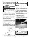
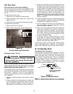
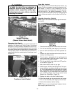
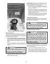
Roll-out Protection Control
If the flames from the burners are not properly drawn
into the heat exchanger, a protection device will open,
causing the gas valve to close. The protection device is
located on the manifold assembly (Figure 14).