26
Burners
WARNING
To avoid personal injury or death due
to electrical shock, do not remove any
internal compartment covers or attempt
any adjustment. Contact a qualified ser-
vicer at once if an abnormal flame ap-
pearance should develop.
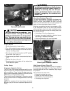
At least once a year, prior to or during the heating sea-
son, make a visual check of the burner flames.
NOTE: This will involve removing and reinstalling the
right front door on the unit, which is held by several
screws. If you are uncertain about your ability to do
this, contact a qualified servicer.
If a strong wind is blowing, it may alter the airflow pat-
tern within the furnace enough that an inspection of the
burner flames is not possible.
The inspection of the burner flames must be performed
with the heat shield in place. Only a qualified servicer
should ever remove the heat shield from the manifold
assembly.
For further information on the yearly inspection, con-
sult the User Manual. It is recommended that a quali-
fied servicer inspect and service the unit at least once
each year.
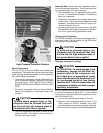
Turn the furnace on at the thermostat. Wait a few min-
utes, since any dislodged dust will alter the normal flame
appearance. Flames should be predominantly blue and
directed into the tubes. They should not be yellow. They
should extend directly outward from the burner ports
without curling downward, floating or lifting off the ports.
XIV. Accessories and Functional
Parts
Accessories
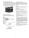
Additional Amana accessories can be purchased to fit
specific application needs. Accessories can be ordered
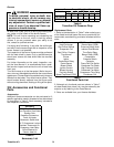
by description in Table 5. Each accessory includes its
own separate instructions.
Accessory
Duct Transition Round
Duct Transition Over/Under
Rooftop Curb
Downflow Economizer
Fresh Air Intake
Barometric Relief Hood
50° F Compressor Lockout
Ambient Thermostat Kit
Emergency Heat Relay
Circuit Breaker Kit
Electric Heat Kit
Table 5
Accessory List
Transition Kit
Pressure Drop of Transition Kit
Model
CFM
700 900 1200 1400 1600 1800
PDTROU3A
0.07 0.11 0.19
--- --- ---
PDTROU5A
--- --- --- 0.06 0.08 0.10
Table 6
Transition Kit Pressure Drop
Replacement Parts
1. Refer to the description in Table 7 when ordering any
of the listed functional parts. Be sure to provide the fur-
nace model, manufacturing, and serial numbers with the
order.
Gas Valve BPM Blower Motor (PGC)
Heat Exchanger Blower Motor (PGB)
Gas Orifice, Natural Pressure Switch Hose
Evaporator Coil Induced Draft Blower
Gas Orifice, Propane Time Delay Relay
Transformer Blower Relay (PGB)
Burner Compressor
Ignitor Pressure Switch
Combustion Relay Contactor
Flame Sensor Flame Roll-Out Switch
Blower Wheel Condenser Fan Blade
Ignition Control High Pressure Cutout
Blower Housing Condenser Fan Motor
Fan/Limit Switch Compressor Time Delay
Speed Tap Board (PGC) Condenser Coil
Table 7
Functional Parts List
2. Although only functional parts are shown in Table 7,
all sheet metal parts, doors, etc. may be ordered by de-
scription or by referring to the Parts Manual.
3. Parts are available from your Amana distributor.


