


20
Gas Input And Pressures
Gas supply pressure and manifold pressure with the
burners operating must be as specified on the rating
plate.
Checking Gas Pressure
Gas inlet pressure should be checked and adjusted in
accordance to the type of fuel being consumed.
With Power And Gas Off:
1. Connect a water manometer or adequate gauge to
the manifold gas pressure tap of the gas valve.
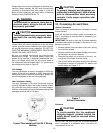
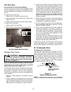
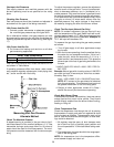
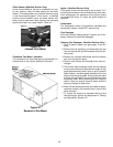
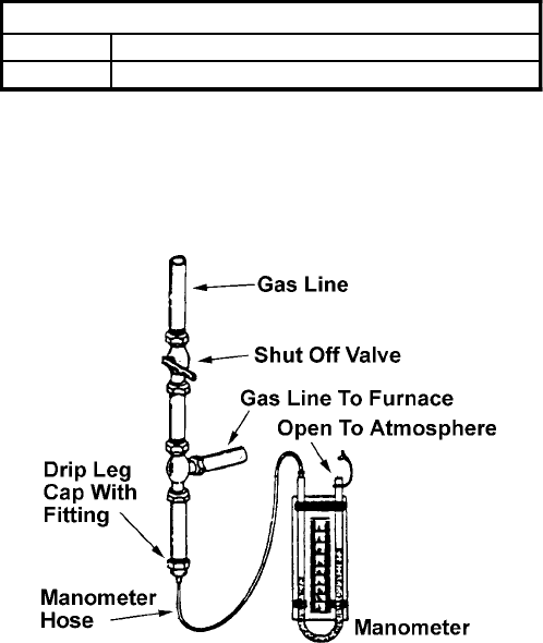
As an alternative method, inlet gas pressure can also
be measured by removing the cap from the dripleg and
installing a predrilled cap with a hose fitting. (See Figure
17).
With Power And Gas On:
2. Put furnace into heating cycle and turn on all other
gas consuming appliances.
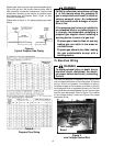
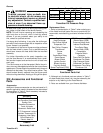
INLET GAS PRESSURE
Natural Min. 5.0" W.C., Max. 10.0" W.C.
Propane Min. 11.0" W.C., Max. 14.0" W.C.
Inlet Gas Pressure Must Not Exceed the Maximum Val-
ues shown in Table Above.
If operating pressures differ from above, make neces-
sary pressure regulator adjustments, check piping size,
etc., and/or consult with local utility.
Figure 17
Measuring Inlet Gas Pressure
Alternate Method
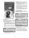
Check The Manifold Pressure
A tapped opening is provided in the gas valve to facili-
tate measurement of the manifold pressure. A U Tube
manometer having a scale range from 0 to 12 inches of
water should be used for this measurement. The mani-
fold pressure must be measured with the burners oper-
ating.
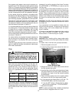
To adjust the pressure regulator, remove the adjustment
screw or cover on the gas valve. Turn out (counterclock-
wise) to decrease pressure, turn in (clockwise) to in-
crease pressure. Only small variations in gas flow should
be made by means of the pressure regulator adjustment.
In no case should the final manifold pressure vary more
than plus or minus 0.3 inches water column from the
specified pressure. Any major changes in flow should
be made by changing the size of the burner orifices.
Check The Gas Input (Natural Gas Only)
NOTE: On outdoor equipment, the gas input will vary
with the temperature of the gas. Rated input will be ob-
tained at approximately 10° F. With warmer ambient and
gas temperatures, the input will decrease. Example: At
70° F the input will decrease 12%.
To measure the gas input using the gas meter proceed
as follows:
1. Turn off gas supply to all other appliances except
the furnace.
2. With the furnace operating, time the smallest dial on
the meter for one complete revolution. If this is a 2
cubic foot dial, divide the seconds by 2; if it is a 1
cubic foot dial, use the seconds as is. This gives the
seconds per cubic foot of gas being delivered to the
furnace.
3. INPUT=GAS HTG VALUE x 3600 / SEC. PER CU-
BIC FOOT
Example: Natural gas with a heating value of 1000 BTU
per cubic foot and 34 seconds per cubic foot as deter-
mined by Step 2, then:
Input = 1000 x 3600 / 0.34 = 106,000 BTU per Hour.
NOTE: BTU content of the gas should be obtained
from the gas supplier. This measured input must not
be greater than shown on the unit rating plate.
4. Relight all other appliances turned off in Step 1
above. Be sure all pilot burners are operating.
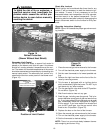
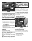
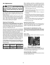
Check Main Burner Flame
Flames should be stable, soft and blue, (dust may cause
orange tips but they must not be yellow). They should
extend directly outward from the burner without curling,
floating or lifting off.
Check Temperature Rise
Check the temperature rise through the unit by placing
thermometers in supply and return air registers as close
to the furnace as possible. Thermometers must not be
able to see the furnace heat exchangers, or false read-
ings could be obtained.
1. All registers must be open; all duct dampers must
be in their final (fully or partially open) position and
the unit operated for 15 minutes before taking read-
ings.
2. The temperature rise must be within the range speci-
fied on the rating plate.
NOTE: Air temperature rise is the temperature differ-
ence between supply and return air.