


28
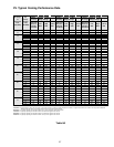
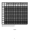
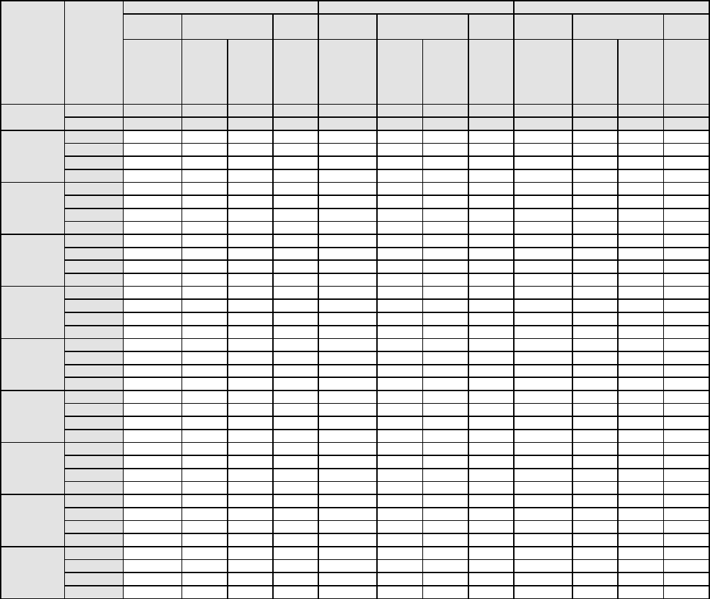
Outdoor Indoor PGC42 PGC48 PGC60 and PGB58
Air Temp.
at
Air
Temp.
Indoor
Air Temp.
Pressure @ Unit
Gauge Fittings
Amps
Indoor
Air Temp.
Pressure @ Unit
Gauge Fittings
Amps
Indoor
Air Temp.
Pressure @ Unit
Gauge Fittings
Amps
Condenser
Inlet
(Dry Bulb)
at Evap.
Inlet
(Wet Bulb)
Difference
Between
Coil Inlet
and Outlet
Low
Side
High
Side
Total to
Unit
Difference
Between
Coil Inlet
and Outlet
Low
Side
High
Side
Total to
Unit
Difference
Between
Coil Inlet
and Outlet
Low
Side
High
Side
Total to
Unit
A BCDEBCDEBCDE
° F. ° F. ° F. PSIG PSIG Amps ° F. PSIG PSIG Amps ° F. PSIG PSIG Amps
77 7 86 332 23.1 8 88 327 23.8 9 83 343 34.9
115 72 12 85 331 23.1 13 88 327 23.8 15 83 342 34.8
67 18 85 332 23.1 18 88 327 23.8 21 82 342 34.7
62 23 84 332 23.2 24 87 326 23.7 26 81 341 34.6
77 8 85 313 22.2 8 88 308 23.2 10 82 323 33.3
110 72 13 85 313 22.2 13 87 308 23.2 15 82 322 33.2
67 18 84 312 22.1 18 87 308 23.1 21 81 322 33.2
62 23 83 311 22.1 24 86 307 23.1 27 80 321 33.1
77 8 84 294 21.3 8 87 291 22.5 10 82 303 31.8
105 72 13 84 293 21.2 13 86 290 22.5 15 81 303 31.8
67 18 83 294 21.3 18 86 290 22.5 21 80 303 31.8
62 23 82 293 21.2 24 85 290 22.4 27 80 302 31.7
77 8 84 277 20.4 8 86 274 21.9 10 81 285 30.5
100 72 13 83 276 20.4 13 86 273 21.9 15 80 285 30.4
67 18 83 275 20.4 19 85 273 21.8 21 80 285 30.5
62 24 82 274 20.3 24 84 272 21.8 27 79 284 30.4
77 8 83 259 19.6 8 85 256 21.3 10 80 268 29.2
95 72 13 82 258 19.6 13 85 257 21.2 16 80 267 29.2
67 18 82 257 19.5 19 84 256 21.2 22 79 267 29.2
62 24 81 256 19.5 25 84 255 21.1 28 78 266 29.1
77 8 82 241 18.8 8 84 240 20.6 10 79 251 28.1
90 72 13 82 241 18.8 14 84 240 20.6 16 79 250 28.0
67 19 81 240 18.8 19 83 240 20.6 22 78 250 28.0
62 24 80 240 18.8 25 83 239 20.5 28 77 249 27.9
77 8 82 226 18.1 9 84 225 20.0 11 79 234 27.0
85 72 13 81 224 18.1 14 83 225 20.0 16 78 234 26.9
67 19 81 225 18.1 19 83 224 20.0 22 78 233 26.9
62 24 80 223 18.0 25 82 224 19.9 28 77 232 26.8
77 8 81 211 17.5 9 83 200 19.4 11 78 218 25.9
80 72 13 81 210 17.5 14 82 210 19.4 16 78 218 25.9
67 19 80 211 17.5 20 82 209 19.4 22 77 218 25.9
62 24 79 208 17.4 25 81 209 19.3 28 76 217 25.8
77 9 80 196 16.9 9 82 196 18.8 11 78 204 25.0
75 72 14 80 196 16.9 14 82 196 18.8 16 77 203 24.9
67 19 79 194 16.8 20 81 195 18.8 22 76 203 24.9
62 25 79 194 16.8 25 80 195 18.8 28 76 202 24.8
Table 8B
A Columns - All data based on indoor dry bulb of 80° F and rated air flow. As indoor dry bulb temperature increases, a slight increase wil
l occur in indoor air temperature differential
between inlet and outlet. Low and high side pressures and power will not change.
B Columns - A properly operating unit should be within ±3° F of the typical (dry bulb) value shown.
C Columns - A properly operating unit should be within ±3 PSIG of the typical value shown.
D Columns - A properly operating unit should be within ±7 PSIG of the typical value shown.
E Columns - A properly operating unit should be within ±2 amps of the typical value shown.