


22
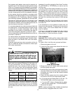
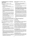
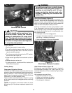
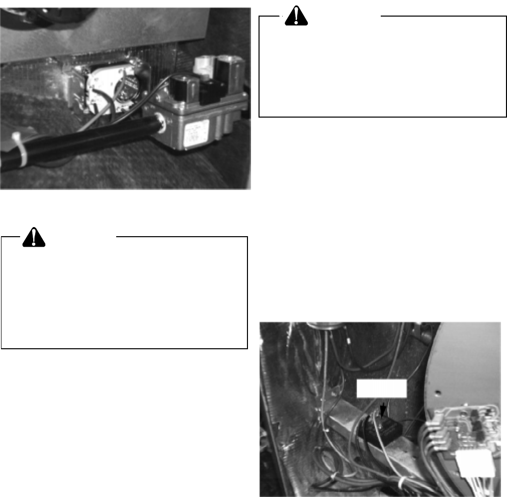
Figure 18
Fan and Limit Control
CAUTION
This unit should not be used as a “con-
struction heater” during the finishing
phases of construction on a new struc-
ture. This type of use may result in pre-
mature failure of the unit due to extremely
low return air temperatures and exposure
to very dirty atmospheres.
To Turn Off Unit
1. Set the thermostat to lowest setting.
2. Turn off the electrical power supply to the furnace.
3. Remove the right hand door on the front of the fur-
nace by removing screws.
4. Turn the gas control valve knob to the OFF position.
Do not force. See Figure 16.
5. Close manual gas shutoff valve external to the fur-
nace.
6. Replace the door on the unit.
7. If cooling and/or air circulation will be desired, turn
ON the electrical power.
Cooling Startup
Compressor Protection Devices
The PGC and PGB includes components which are de-
signed to protect the compressor against abnormal op-
erating conditions. These include the short cycle pro-
tector, external compressor protector (PGC24-42, 60 and
PGB58 only), and high pressure cutout.
These controls reset automatically. Excessive cycling
of the controls should be investigated before continuing
operation.
(NOTE: The operation of the indoor blower will not be
affected by any of the above compressor protection de-
vices.)
WARNING
To avoid personal injury or death, always
disconnect electrical power before in-
specting or servicing the unit. All com-
pressor protection devices reset auto-
matically, energizing the contactor and
outdoor fan.
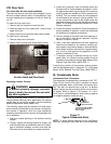
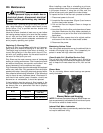
Short Cycle Protector (Figure 19)
The short cycle protector is located in the blower com-
partment. Each time the compressor shuts off for any
reason, the short cycle protector will open. It will take
about 3 to 4 minutes before the short cycle protector will
reset and allow compressor startup to occur.
All wiring connected to the short cycle protector is 24V.
If the compressor cycles on the short cycle protector
without cycling on any of the other compressor protec-
tion devices and before the call for cooling ends, com-
mon causes include:
• Interruption of the line voltage power.
• Improper thermostat installation, defective thermo-
stat wiring, or defective thermostat.
• Rapid adjustments of the room thermostat.
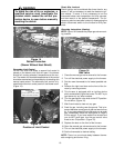
Short Cycle
Protector
Figure 19
Short Cycle Protector Location
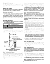
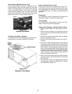
High Pressure Cutout (Figure 20)
An automatic reset high pressure control is located in
the compressor discharge line. (See Figure 20) This
control protects the unit from excessively high refriger-
ant pressure.
High pressures can result from:
• Inoperative outdoor fan motor.
• Outdoor coil restricted with debris.
• Recirculation of hot condenser air.
• Overcharge of refrigerant.