


15
Duct systems and register sizes must be properly de-
signed for the C.F.M. and external static pressure rating
of the unit. Ductwork should be designed in accordance
with the recommended methods of Air Conditioning Con-
tractors of America Manual D (Residential) or Manual Q
(Commercial). All ductwork exposed to the outdoors must
include a weatherproof barrier and adequate insulation.
A duct system should be installed in accordance with
Standards of the National Board of Fire Underwriters for
the Installation of Air Conditioning, Warm Air Heating
and Ventilating Systems, pamphlets No. 90A and 90B.
The warm air supply duct from the unit through a wall
fabricated of combustible material may be installed with-
out clearance. However, minimum clearances for the unit
must be observed as shown in Section III.
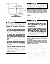
It is recommended that the outlet duct be provided with
an access panel. This access should be large enough
to inspect the air chamber downstream from the heat
exchanger for any smoke or combustion gas leaks. A
cover should be tightly attached to prevent air leaks.
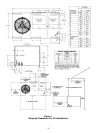
For horizontal airflow, duct flange dimensions on the unit
are shown in Section III.
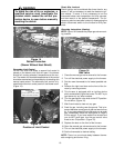
For vertical airflow, the ductwork should be attached to
the roof curb prior to installing the unit. Ductwork dimen-
sions are shown in the Amana PRC roof curb installa-
tion manual.
If desired, supply and return duct connections to the unit
may be made with flexible connections to reduce pos-
sible noise transmission.
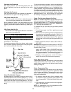
Filters
WARNING
Never operate furnace without a filter in-
stalled as dust and lint will build up on
internal parts resulting in loss of effi-
ciency, equipment damage, and possible
fire.
A return air filter is not supplied with this unit; however,
there must be a means of filtering all of the return air.
For your convenience, this unit contains a factory in-
stalled filter rack. If you choose to install the return air
filter in the unit filter rack, use the appropriate Amana
filter kit or a permanent filter that is properly sized as
follows:
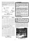
Model Amana Kit #
Required Permanent
Filter Size
PGC24, 30, or 36
PFK3A1 or
PFK3A6
26" x 20" x 1"
PGC42, 48, 60
or PGB58
PFK5B1 or
PFK5B6
32-5/8" x 22-3/8" x 1"
The Amana filter kit includes a permanent filter, door
label, and installation instructions. PFK3A1 and PFK5B1
contain filter, label, and instructions for one unit. PFK3A6
and PFK5B6 contain filters, labels, and instructions for
six units.
Important: If you will be using the Over/Under Transition
Kit, (PDTROU3A or PDTROU5A) you cannot use the
unit filter rack.
If you are using the Over/Under transition kit or are sim-
ply choosing not to use this filter rack, the filter(s) may
be located in the return air duct(s) or return air filter
grille(s). Filters installed external to the unit should be
sized in accordance with their manufacturer recommen-
dations. If you choose to use a throwaway filter it should
be sized for a maximum face velocity of 300 feet per
minute.
Important: The PGC 42 and 48 package units contain
an evaporator drip pan installed on the return air side of
the indoor coil.
If an economizer is to be installed on these units, the
drip pan must be removed. The pan can be removed by
cutting it away. It will not be needed when an econo-
mizer is installed.
If filters are to be installed on these units, they must be
from filter kit PFK5B1 or PFK5B6. The filters in these
kits are sized to fit with the drip pan in place.
Filter Installation
Important: When installing a filter, always make certain
the air flow arrows on the filter point toward the indoor
blower.
To install a filter in the filter rack, proceed as follows:
1. Disconnect power to the unit.
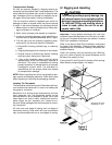
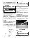
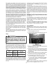
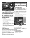
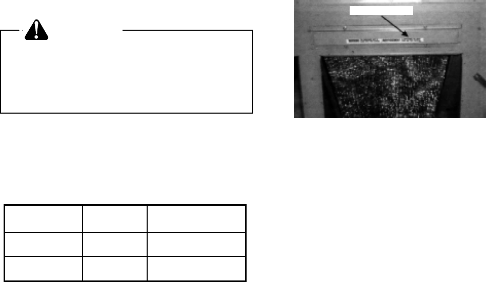
2. Locate the filter access door above the return air
opening. See Figure 9.
Filter Access Door
Figure 9
Filter Access Door
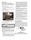
3. Remove the four 5/16" sheet metal screws and set
the filter access door aside.
4. Insert the filter into the filter rack channels and lower
into place. Make sure the filter slides completely to
the bottom so no part of the filter remains outside
the back panel.
5. Return the filter access door to its original position
and secure it with the four sheet metal screws.
6. a. If you are using an Amana filter kit, affix the FIL-
TER ACCESS label to the filter access door.
b. If you are NOT using an Amana filter kit, clearly
mark the filter access door “FILTER ACCESS”.
7. Reconnect the power.
NOTE: A clean permanent filter installed as described
above will have a negligible effect on air flow.