


2
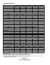
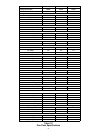
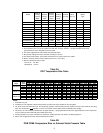
I. Unit Specifications
MODEL PGC24B0452A PGC24B0702A PGC30B0702A PGC36B0702A PGC36B0902A
Cooling Capacity Btuh 24,000 24,000 30,000 36,000 36,000
SEER 12.50 12.50 12.30 12.00 12.00
Heating
Input Btuh 45,000 70,000 70,000 70,000 90,000
Output Btuh 35,000 55,000 55,000 55,000 70,000
AFUE 80.9 80.1 80.1 80.1 80.4
Temperature Rise °F 20-50 30-60 30-60 30-60 40-70
Number of Burners 2 3 3 3 4
Compressor
R.L. Amps 12.9 12.9 15 20 20
L.R. Amps 62.5 62.5 76 90.5 90.5
Condenser Coil
Face Area (sq. ft.) 12.3 12.3 12.3 14 14
Rows Deep 1 1/2 1 1/2 2 2 2
Fins/Inch 13 13 13 13 13
Condenser Fan
Diameter (in.) 20 20 20 20 20
CFM 2670 2670 2700 3060 3060
Condenser Fan Motor
Horsepower 1/8 1/8 1/4 1/4 1/4
R.L. Amps 0.8 0.8 1.2 1.5 1.5
L.R. Amps 1.5 1.5 3 3.4 3.4
Blower Motor
Horsepower 0.5 0.5 0.5 0.5 0.5
R.L. Amps 4.3 4.3 4.3 4.3 4.3
L.R. Amps Protected by redundant electronic control circuits
Blower Wheel Dia. x Width (in.) 10x7 10x7 10x7 10x7 10x7
Rated CFM, Cooling 850 850 1100 1300 1300
Max. External 0.8" wc 0.8" wc 0.8" wc 0.8" wc 0.8" wc
Combustion Blower
Diameter x Width (in.) 4 x 1.25 4 x 1.25 4 x 1.25 4 x 1.25 4 x 1.25
No. 11111
Condenser Blower Motor
H.P. 0.03125 0.03125 0.03125 0.03125 0.03125
F.L. Amps. 0.5 0.5 0.5 0.5 0.5
Press. Switch Setting (" W.C.) -0.65 -0.65 -0.65 -0.65 -0.65
Ignition - Lockout Timing (sec.) 4 4 4 4 4
Flame Sense Current (microamps)
Minimum 11111
Maximum 66666
Evaporator Coil
Face Area (Sq. Ft.) 4 4 4 4 4
Rows Deep 22244
Fins/Inch 16 16 16 12 12
External Filter Size (Sq. Ft.) 3.6 3.6 3.6 3.6 3.6
Drain Line Size (in.) 3/4 3/4 3/4 3/4 3/4
Expansion Device (Cooling) Capillary Capillary Capillary Capillary Capillary
Refrigerant Charge Refer to unit name plate for correct charge
Power Supply** 208/230-60-1 208/230-60-1 208/230-60-1 208/230-60-1 208/230-60-1
Min. Circuit Ampacity 21.3 21.3 24.3 30.8 30.8
Max. Overcurrent Device 30 30 35 45 45
Electrical Entrance Size
Power Supply 1 1/4", 1 1/2", 2" 1 1/4", 1 1/2", 2" 1 1/4", 1 1/2", 2" 1 1/4", 1 1/2", 2" 1 1/4", 1 1/2", 2"
Low Voltage 7/8" 7/8" 7/8" 7/8" 7/8"
Approx. Shipping Weight (lb.) 385 394 418 437 443
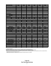
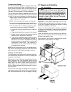
1) United States Installation
2) Specification subject to change without notice. See sales specification sheets for certain BTUH capacities.
3) This PGC series complies with requirements embodied in the American National Standard ANSI-Z21.47 Central Furnaces.
4) Filters are not supplied with units, but filters must be installed in the unit filter rack or in the return air system.
** While the above data is presented as a guide, it is important to electrically connect the unit and properly size overcurrent protection and wires in accordance with the
National Electrical Code and all existing local codes.
Operating tolerance: Minus 5% on 208 VAC, Plus 10% on 208 VAC and 230 VAC, Minus 10% on 230 VAC
Table 1A
Gas Pack Specifications