


21
With a properly designed system, the proper amount of
temperature rise will normally be obtained when the unit
is operated at rated input with the recommended blower
speed.
If the correct amount of temperature rise is not obtained,
it may be necessary to change the blower speed. A
higher blower speed will lower the temperature rise. A
slower blower speed will increase the temperature rise.
NOTE: Blower speed MUST be set to give the correct
air temperature rise through the furnace as marked on
the rating plate.
Important Note: If an installation uses a different blower
speed for cooling than is used for heating, do not set the
thermostat fan switch to ON (constant fan operation)
during the heating season without first confirming the
cooling fan speed will give a temperature rise within the
limits listed on the unit nameplate. Temperature rises
outside the limits listed could result in premature heat
exchanger failure.
Checking External Static Pressure
The total external static pressure must be checked on
this unit to determine if the airflow is correct.
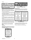
Changing Blower Speeds (PGC Units)
WARNING
To avoid personal injury or death due to
electric shock, remove electrical power
from the unit before changing speed taps
on the blower motor.
PGC-B models include a BPM (brushless permanent
magnet) motor. Under identical conditions, it operates
at a lower power consumption than most PSC motors.
Within the allowable range of external static pressures,
the BPM motor will automatically adjust its RPM to de-
liver the CFM listed in the blower performance table. As
static pressure increases, the RPM, current draw, and
operating sound level of the motor will also increase.
External static pressures in excess of those listed on
the nameplate may result in unsatisfactory operation,
equipment damage, and/or loss of warranty coverage.
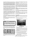
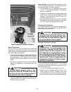
The PGC-B models also include a speed tap board lo-
cated on the blower housing. The speed tap settings
have been factory selected according to unit size and
performance. Field select taps are provided on the speed
tap board to assist the final installer. The ADJ. tap is
factory set for normal (NORM) operation. Three LED’s
are provided on the speed tap board. These lights indi-
cate to the servicer which mode of operation the motor
is experiencing, that is Heating (W1), Fan Only (G) or
Cooling (Y and G).
Refer to the wiring diagram on the unit to verify speed
tap settings.
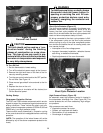
Changing Blower Speeds (PGB Units)
WARNING
To avoid personal injury or death due to
electric shock, remove electrical power
from the unit before changing speed taps
on the blower motor.
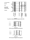
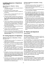
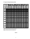
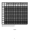
A multi-speed motor is used in the furnace blower. It
provides easy speed selection for both heating and cool-
ing air flow. Section II shows the CFM and E.S.P. rela-
tionship for proper selection of heating and cooling
speeds. Cooling speed should be set for about 400 CFM
per ton cooling capacity.
Refer to the Wiring Diagram on the furnace to connect
the proper wires to the correct motor leads. All unused
motor leads must be taped or securely covered with wire
nuts.
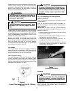
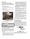
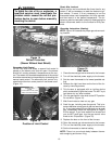
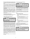
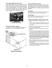
Check Limit And Fan Control
1. Check limit control (Figure 18) operation after 15
minutes of operation by blocking the return air
grille(s).
a. After several minutes the main burners must go
OFF. Blower will continue to run.
b. Remove air restrictions and main burners will re-
light after a cool down period of a few minutes.
2. Adjust the thermostat setting below room tempera-
ture.
a. Main burners must go off.
b. Circulating Air Blower should continue to run briefly
until supply air temperature drops to approximately
90-100° F.
Fan and limit controls are preset at the factory. The con-
trol is set for the fan to go off at 90-100° F:
NOTE: If necessary, adjust fan ON/OFF settings to ob-
tain satisfactory comfort level. The fan comes on at ap-
proximately 125° F.
WARNING
To avoid personal injury, property dam-
age, fire, or premature failure of the heat
exchanger, do not adjust the limit con-
trol, which is set at the factory.