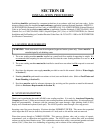
13
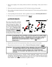
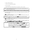
1. Remove the wrappings of the vending machine and check for transit damage. Notify carrier if there is
damage.
2. Skid can be removed by unscrewing four (4) 5/16” skid bolts at the legs of the machine.
3. Place machine at the intended location and, if required, adjust the 3/4” bolts at the legs until the machine is
level and stable.
4. Connect plumbing inlet and outlet lines. Refer to guidelines in the section “SITE REQUIREMENTS.”
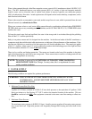
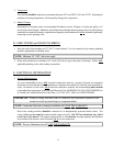
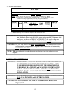
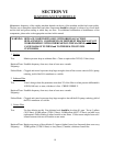
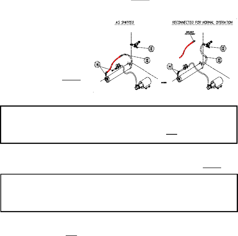
5. Reconnect reverse osmosis (R.O.) membrane (refer to page 13).
ATTENTION
The reverse osmosis (R.O.) membrane
in this machine is filled with a preservative
solution and plugged for shipping. The
two lengths of tubing illustrated below will
have to be reconnected before machine
start-up. (Refer to diagrams to right).
Refer to “Miscellaneous Maintenance
Technique, Section C” on page 35 of
the installation manual for tubing removal
and attachment technique. Push tubing
into fittings firmly to prevent leakage.
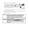
CAUTION: WEAR PROTECTIVE CLOTHING, GLOVES, and SAFETY GLASSES WHEN
RECONNECTING TUBING. THE PRESERVATIVE SOLUTION CONTAINS
SODIUM BISULFITE and GLYCERINE and MAY CAUSE SKIN and EYE
IRRITATION IN SOME INDIVIDUALS. WIPE UP ALL SPILLS
IMMEDIATELY.
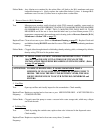
6. Open the main water ball valve located inside the cabinet at the water inlet of the machine.
7. Plug machine into the electrical outlet. (Refer to Electrical Information, Section E on page 11).
WARNING: THE MACHINE IS SHIPPED WITH A PRESERVATIVE SOLUTION MADE
OF SODIUM BISULFITE and (IN THE WINTER MONTHS) GLYCERINE.
MAKE SURE THE SYSTEM IS THOROUGHLY PURGED BEFORE
LETTING ANYONE DRINK THE DISPENSED WATER. (SEE STEP #9 and
STEP #10).
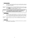
8. The display should blink the message: “SYSTEM” “PURGE” “DO NOT” “DRINK.” Purge cycle starts
automatically. Clear the dispensing bay of obstacles, as water will come out of the dispensing valve and into
the drain basin. Discard ALL water dispensed until purge cycle is over. Cycle is over when the display
blinks “INSERT” and “COIN” or the amount for 1 gallon (3.78 liters).


