


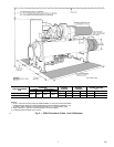
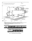
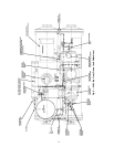
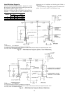
Refer to Fig. 10 unless otherwise specified.
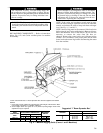
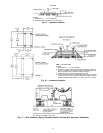
1. Turn all 4 vessel separation feet to the lowered position
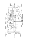
(Fig. 11).
2. Disconnect and/or cut the following lines, as required:
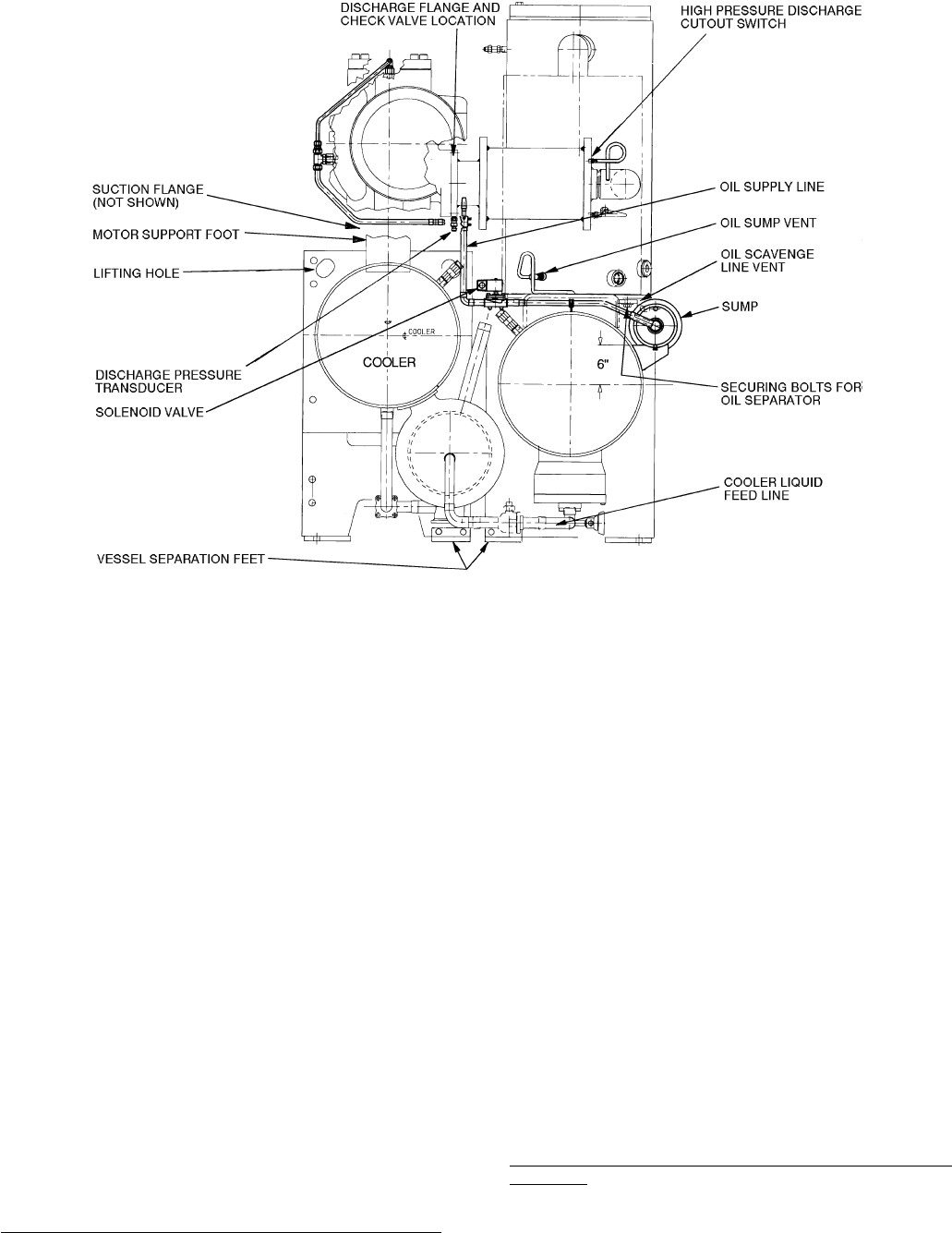
a. cooler liquid feed.
b. motor cooling supply from condenser.
c. liquid injection to compressor.
d. bubble line to float chamber (not shown).
e. optional hot gas bypass and associated solenoid valve
wiring (not shown).
f. motor power cables from optional unit mounted starter
lugs (not shown).
3. Separate compressor by disconnecting the following:
a. discharge flange from compressor (remove the check
valve).
b. oil supply line to compressor and associated solenoid
valve wiring.
4. Cover all openings.
5. Be sure all wiring is properly marked. Detach all trans-
ducers, switches, and sensor wires. Remove all wire ties
required to remove wires from the cooler to the con-
denser. Do not cut the wires.
6. Disconnect the rabbet fit connectors on the tube sheets.
7. Rig vessels apart.
To Separate Compressor from Cooler (Frame 4 Machines)
1. Unbolt the suction flange (Fig. 11).
2. Disconnect the following lines:
a. motor cooling to motor (Fig. 10).
b. motor cooling drain (Fig. 11).
c. optional economizer gas line to compressor rotors
(Fig. 10).
d. liquid injection to compressor (Fig. 10).
3. Separate compressor from oil supply system by discon-
necting the following:
a. discharge flange from compressor and remove check
valve (Fig. 10).
b. oil supply line to compressor and associated solenoid
valve wiring (Fig. 10).
4. Cover all openings.
5. Be sure the following electrical connections are
disconnected:
a. motor power cables from optional unit-mounted starter
lugs (not shown).
b. motor winding temperature sensor (Fig. 10).
c. slide valve increase and decrease capacity control so-
lenoid valves (Fig. 10).
d. optional variable VI solenoid valves (Fig. 10).
e. discharge (condenser) pressure transducer (Fig. 10).
6. Unbolt motor support foot (Fig. 10).
7. Rig compressor.
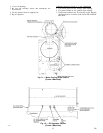
To Separate Oil Separator from Condenser (Frame 4
Machines)
Refer to Fig. 12 unless otherwise specified.
1. Separate the compressor and oil separator by disconnect-
ing the following:
a. discharge flange from compressor (secure the check
valve). See Fig. 11.
b. oil supply line from separator to compressor.
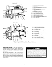
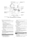
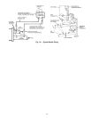
Fig. 8 — 23XL Drive End View (Frame 1 and 2 Machines)
12