IMPORTANT: Do not insulate terminals until wiring
arrangement has been checked and approved by
Carrier start-up personnel.Also, make sure correct phas-
ing is followed for proper motor rotation.
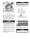
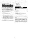
INSULATE MOTOR TERMINALS AND LEAD WIRE
ENDS — Insulate compressor motorterminals, lead wire ends,
and electrical wires to prevent moisture condensation and
electrical arcing. Obtain insulation material from machine
shipping package (located inside the motor terminal box) con-
sisting of 3 rolls of insulation putty and one roll of vinyl
tape.
1. Insulate each terminal by wrapping with one layer of in-
sulation putty.
2. Overwrap putty with 4 layers of vinyl tape.
NOTE: Installer is responsible for any damage caused by
improper wiring between starter and compressor motor.
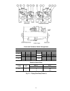
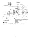
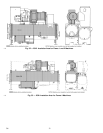
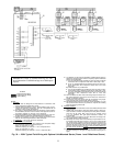
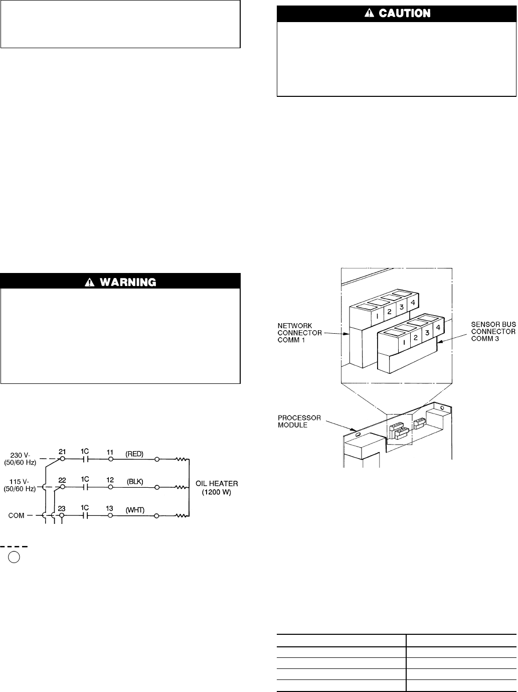
CONNECT POWER WIRE TO OIL HEATER CONTAC-
TOR (FRAME 1 AND 2) — Connect control power wiring
between the oil heater contactor terminals (Fig. 29) and
terminals LL1 and LL2 on the field wiring strip in the
compressor motor starter. Refer to Fig. 29 and wiring label
on the chiller power panel
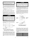
Voltage to terminals LL1 and LL2 comes from a con-
trol transformer in a starter built to Carrier specifi-
cations. Do not connect an outside source of control
power to the compressor motor starter (terminals LL1
and LL2). An outside power source will produce dan-
gerous voltage at the line side of the starter, because
supplying voltage at the transformer secondary termi-
nals produces input level voltage at the transformer
primary terminals.
NOTE: The voltage selector switch in the machine power
panel is factory set for 115 v control power source. When a
230 v control power source is used, set the voltage selector
switch at 230 v.
CONNECT COMMUNICATION AND CONTROL WIR-
ING FROM STARTER TO POWER PANEL — Connect
control wiring from main motor starter to the machine power
panel. All control wiring must use shielded cable. Also,
connect the communications cable. Refer to the job wiring
diagrams for cable type and cable number. Make sure the
control circuit is grounded in accordance with applicable
electrical codes and instructions on machine control wiring
label.
The optional hot gas bypass valve is factory wired for
115 volts. If 230 v is used for control voltage, discon-
nect the red wire from the piggy-back terminal oil heater
contactor terminal 23 and yellow wire from the piggy-
back on pilot relay 3C terminal No. 4. Then connect
the red and yellow wires together with a splice
connector.
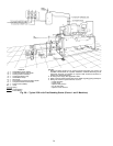
CARRIER COMFORT NETWORK INTERFACE — The
Carrier Comfort Network (CCN) communication bus wiring
is supplied and installed by the controls/electrical contractor
(if required). The wiring consists of shielded, 3-conductor
cable with drain wire.
The system elements are connected to the communication
bus in a daisy chain arrangement. The positive pin of each
system element communication connector must be wired to
the positive pins of the system element on either side of it.
The negative pins must be wired to the negative pins. The
signal ground pins must be wired to the signal ground pins.
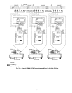
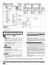
See Fig. 30 for location of the CCN network connector
(COMM1) on the processor module.
NOTE: Conductors and drain wire must be 20 AWG
(American Wire Gage) minimum stranded, tinned cop-
per. Individual conductors must be insulated with PVC,
PVC/nylon, vinyl, Teflon, or polyethylene. An aluminum/
polyester 100% foil shield and an outer jacket of PVC, PVC/
nylon, chrome vinyl, or Teflon with a minimum operat-
ing temperature range of −4 F to 140 F (−20 C to 60 C)
is required. See table below for cables that meet the
requirements.
MANUFACTURER CABLE NO.
Alpha 2413 or 5463
American A22503
Belden 8772
Columbia 02525
LEGEND
Field Wiring
Power Panel Component Terminal
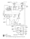
Fig. 29 — Oil Heater and Control Power
Wiring Diagram (Frame 1 and 2 Machines)
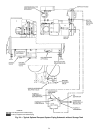
Fig. 30 — Carrier Comfort Network
Communication Bus Wiring
29 796
→


