


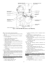
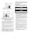
Install Machine Supports
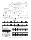
INSTALL STANDARD ISOLATION — Figures 13-18 show
the position of support plates and shear flex pads that form
the standard machine support system.
INSTALL OPTIONAL OR ACCESSORY ISOLATION (if
required) — Uneven floors or other considerations may
dictate the use of soleplates and leveling pads. Refer to
Fig. 13-18.
Level machine by using jacking screws in isolation sole-
plates. Use a level at least 24 in. (600 mm) long.
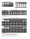
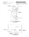
DIMENSION
HEAT EXCHANGER SIZE
10 or 11 20 or 21
ft-in. mm ft-in. mm
A 4-5
1
⁄
4
1353 4-7
1
⁄
4
1403
B 4-4
1
⁄
2
1334 4-6
1
⁄
2
1384
C 1-0
3
⁄
8
314 1-1
3
⁄
8
340
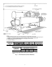
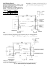
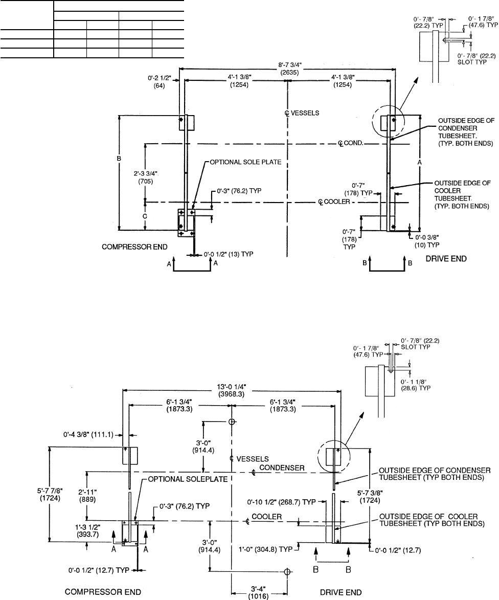
NOTES:
1. Dimensions in ( ) are in millimeters.
2. Use grout and package components to establish the level base line.
3. If chiller is set on concrete pad, electrical contractor is to locate conduit stub-ups outside of pad.
Approximate
location shown.
4. See Fig. 15 and 16 for additional information.
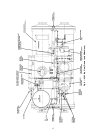
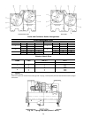
Fig. 13 — 23XL Machine Footprint (Frame 1 and 2 Machines)
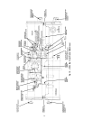
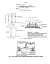
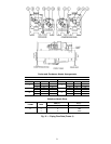
NOTES:
1. Dimensions in ( ) are in millimeters.
2. Use grout and package components to establish the level base line.
3. If chiller is set on concrete pad, electrical contractor is to locate conduit stub-ups outside of pad.
Approximate
location shown.
4. See Fig. 15 and 16 for additional information.
Fig. 14 — 23XL Machine Footprint (Frame 4 Machine)
16