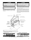
The compressor is heavy. To avoid bodily injury, lift
the compressor only by using cables or slings. Do not
lift the compressorusing threaded eyebolts.Metric threaded
eyebolts are provided only for lifting individual com-
pressor castings.
IMPORTANT: Only a qualified service technician
should disassemble and reassemble the machine.After
reassembly, the machine must be dehydrated and leak
tested.
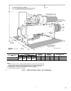
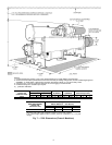
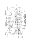
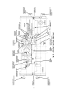
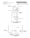
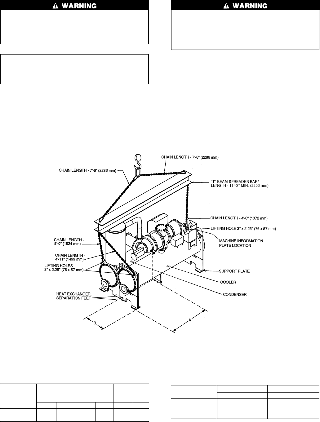
RIG MACHINE COMPONENTS — Refer to instructions
below, Fig. 8-12, and Carrier certified prints for machine
disassembly.
Do not attempt to cut refrigeration lines or disconnect
flanges or fittings while machine is under pressure. Cut-
ting lines or disconnecting flanges or fittings can result
in personal injury or damage to the unit. Be sure both
refrigerant and oil charge are removed from the ma-
chine before separating the components.
NOTE: If the cooler and condenser vessels must be sepa-
rated, the heat exchanger separation feet must be unbolted,
rotated, and rebolted in order to keep each heat exchanger
level. See Fig. 4, 5, and 8-12.
NOTE: Sensor wiring must be disconnected. Label each wire
before removal (see Carrier certified prints). Remove all trans-
ducer and thermistor wires at the sensor. Clip all wire ties
necessary to remove the wires from the heat ex-
changers. Remove the control wiring and oil heater wiring
(Frame 1 and 2 machines) at the power panel and the main
motor leads at the starter lugs before disconnecting the starter
from the machine.
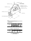
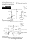
*Carrier recommends that ‘‘I’’ Beam Spreader Bars be field supplied and installed.
NOTES:
1. Each chain must be capable of supporting the entire weight of the machine. Maxi-
mum weight of machine is 13,200 lbs (5940 Kg).
2. Chain lengths shown are typical for 15 ft (4572 mm) lifting height. Some minor
adjustment may be required.
HEAT
EXCHANGER
SIZE
CENTER OF GRAVITY —
APPROXIMATE DIMENSIONS
MAXIMUM
WEIGHT
A (Length) B (Width)
ft-in. mm ft-in. mm lb Kg
10 or 11 3- 8 1117 1-11 572 11,810 5357
20 or 21 3-10 1161 2- 0 600 13,200 5940
Suggested ‘‘I’’ Beam Spreader Bar*
OPTIONS
ENGLISH SI
in. x lb/ft cm x N/m
1 S12 x 31.8 S30 x 464
2 S10 x 35 S25.4 x 511
3 W12 x 22 W30 x 321
4 W10 x 25 W25.4 x 365
Fig. 4 — Machine Rigging Guide (Frame 1 and 2 Machines)
5 796
→


