


For adequate and long-lasting machinesupport, proper grout
selection and placement is essential. Carrier recommends that
only epoxy-type grout be used for machine installation. Fol-
low manufacturer’s instructions in applying grout.
1. Check machine location prints for required grout
thickness.
2. Carefully wax jacking screws for easy removal from grout.
3. Grout must extend above the base of the soleplate and
there must be no voids in grout beneath the plates.
4. Allow grout to set and harden, per manufacturer’s in-
structions, before starting machine.
5. Back jacking screws off leveling pads after grout has
hardened.
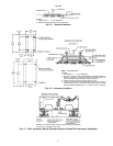
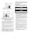
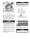
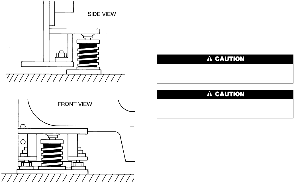
INSTALL SPRING ISOLATION — Field-supplied spring
isolators may be placed directly under machine support plates
or located under machine soleplates. See Fig. 17. Consult
job data for specific arrangement. Low profile spring isola-
tion assemblies are recommended so that the machine is kept
at a convenient working height inside of the tube sheet.
Obtain specific details on spring mounting and machine
weight distribution from job data. Also, check job data for
methods for supporting and isolating pipes that are attached
to the spring isolated machines.
Connect Piping
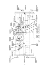
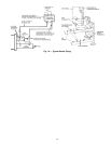
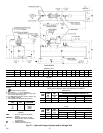
INSTALL WATER PIPING TO HEAT EXCHANGERS —
Install piping using job data, piping drawings, and proce-
dure outlined below. A typical piping installation is shown
in Fig. 19.
Factory-supplied insulation is not flammable but can be
damaged by welding sparks and open flame. Protect in-
sulation with a wet canvas cover.
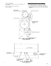
Remove chilled and condenser water sensorsbefore weld-
ing connecting piping to water nozzles. Refer to Fig. 2
and 3. Replace sensors after welding is complete.
1. If the machine is a nozzle-in-head arrangement, offset pipe
flanges to permit removal of waterbox cover for main-
tenance and to provide clearance for pipe cleaning. No
flanges are necessary with marine waterboxes; however,
water piping should not cross in front of the waterbox or
access will be blocked off.
2. Provide openings in water piping for required pressure
gages and thermometers. Openings should be at least 6 to
10 pipe diameters from the waterbox nozzle. For thor-
ough mixing and temperature stabilization, wells in the
leaving water pipe should extend inside pipe at least
2 in. (50 mm).
3. Install air vents at all high points in piping to remove air
and prevent water hammer.
4. Install pipe hangers where needed. Make sure no weight
or stress is placed on waterbox nozzles or flanges.
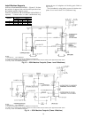
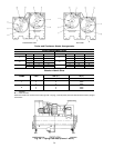
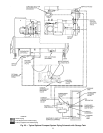
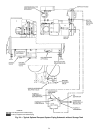
5. Water flow direction information is shown in Fig. 20 and
21.
NOTE: Entering water is always the lower of the two
nozzles. Leaving water isalways the upper nozzle for cooler
or condenser.
6. Water flow switches must be of vapor-tight construction
and must be installed on top of the pipe in a horizontal
run and at least 5 pipe diameters from any bend.
Differential pressure type flow switches may be con-
nected at the nozzle of the waterbox.
7. Install waterbox vent and drain piping in accordance with
individual job data. All connections are
3
⁄
4
-in. FPT.
8. Install waterbox drain plugs in the unused waterbox drains
and vent openings.
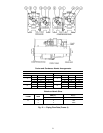
9. Install water piping to the optional pumpout system con-
denser storage tank as shown in Fig. 20-25.
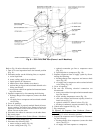
NOTE:Afield suppliedand installed lowprofile isolation issuggested
to keep operation height low.
Fig. 18 — Typical Low Profile Isolation Assembly
(Field Supplied and Installed)
18